105
Merrychef conneX
®
service and repair manual
7 Circuit boards and diagrams
Back to contents >
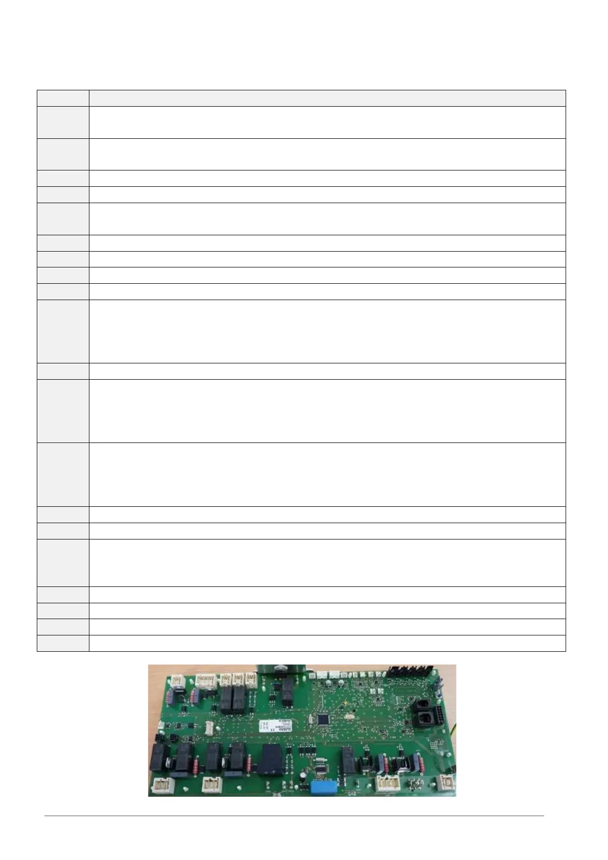
7 CIRCUIT BOARDS A ND DIAGRAMS
Wire 15 – Neutral (US L2) from top mains filter
Wire 16 – Live to Switch Mode Power Supply
Wire 17 – Neutral (US L2) to SMPS
Wires 58 & 59 – cooling fan supply
Stirrer motor(s)
Wire 64 – Live to VFD (fan speed controller)
Wire 65 – Neutral (US L2) to VFD
Wire 10 – Live from F3
Wire 29 – Live to heating element(s)
Wire 24 – Live from door SW3 for microwave circuit(s)
Wire 13 – Neutral (US L2) from F6
Wire 20 – Live from door SW2
Wire 22 – Neutral (US L2) from door SW1
Wire 23 – Live to door SW3
RH / Rear HV Transformer
Wire 31 – terminal 0. Neutral (US L2)
Wire 35 – terminal 200/208. Live
Wire 36 – terminal 230/240. Live
LH / Front HV Transformer
Wire 44 – terminal 0. Live
Wire 49 – terminal 200/208. Neutral (US L2)
Wire 50 – terminal 230/240. Neutral (US L2)
X412 Wire 21 – Neutral (US L2) to door SW1
Not used
Wire 18 +
Wire 19 -
Not used – Linked out (jumper)
Cavity overheat thermostat. Wires 70 & 69
Centre / RH Magnetron overheat thermostat. Wires 72 & 71
 Loading...