WATER
HEATER
CONNECTIONS
WATER
HEATER
INSTALLATIONS
This engine is equipped with connections for the plumbing
of
engine coolant
to
heat
an
on-board
water
heater.
The
water
heater
should
be
mounted
in
a convenient location
either
in
a
high or low'position
in
relation to the engine, so that the con-
necting
hoses
from
the
heater
to
the
engine
can
run
in
a
rea-
sonably direct line without any loops which might trap air.
Hoses should rise continuously from their low point at the
heater to the engine so that air
wiII
rise naturally from the
heater to the engine.
If
trapped air is able to rise to the heater,
then an air bleed petcock must
be
installed at the higher fit-
ting on the heater for bleeding air while filling the system.
NOTE:
If
any ponion
of
the heating circuit rises above the
engine:r
closed
cooling
system
pressure
cap,
then
a
pressur-
ized (aluminum)
remote
expansion tank (Kit #024177) must
be
installed
in
the
circuit
to
become
the
highest
point.
Tee
the
remote
expansion
tank
into
the
heater
circuit,
choosing
the
higher
of
the
two connections for
the
retum.
Tee
at
the
heater,
and plumb a single
line
up
to
the tank's location and
the
other back
to
the
engine
s
return.
Install
the
remote
expansion
tank
in
a
c.ollvenient
location so
the
fresh
water
coplant level
can
easily
be
checked.
The
remote expansion
.tank
will now serve as a check and system fill point.
The
plastic coolant recovery
tank
is
not used
when
the
remote
expansion
tank
kit
is
installed, since
this
tank
serves
the
same
function.
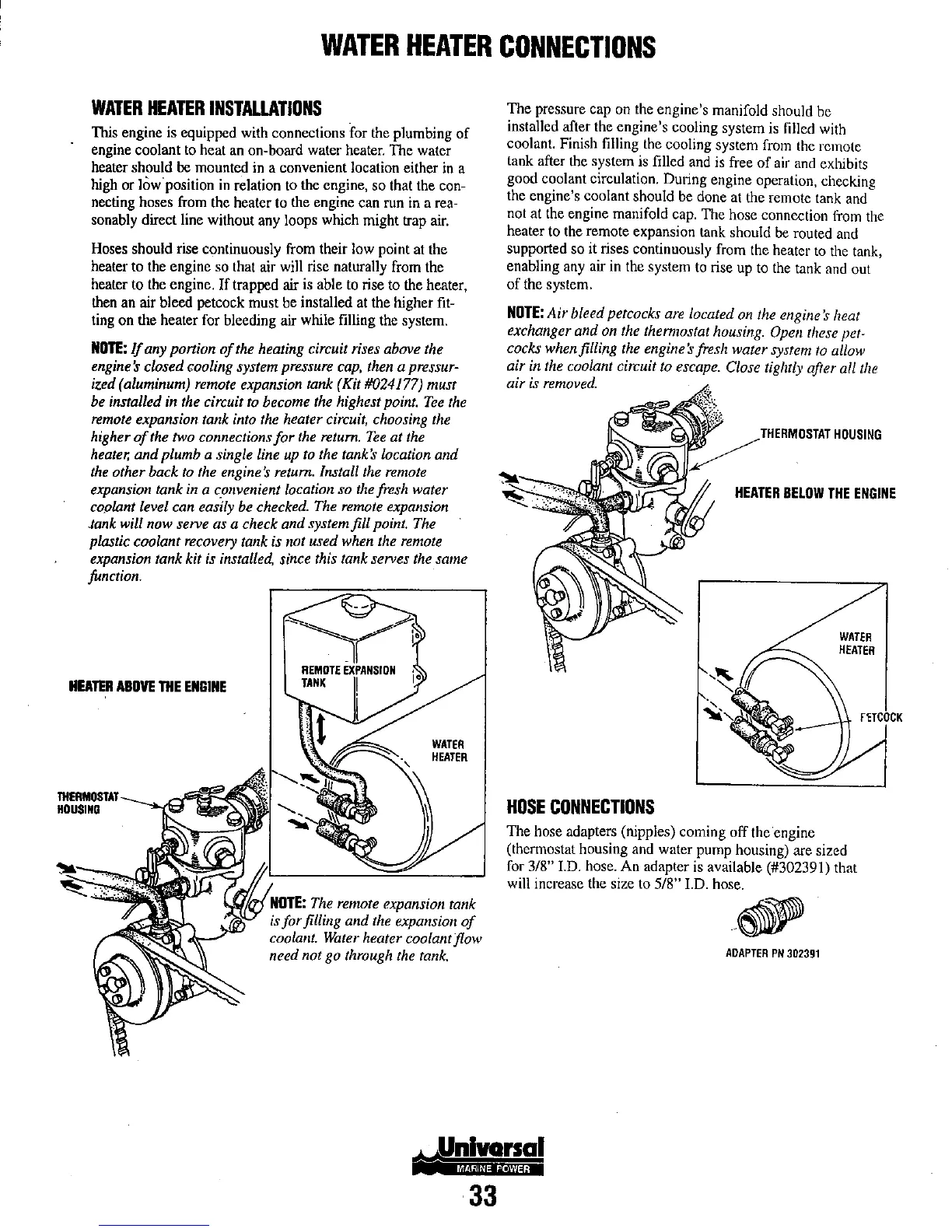
HEATER
ABOVE
THE
ENGINE
WATER
HEATER
NOTE:
The
remote
expansion tank
is
for filling and
the
expansion
of
coolant.
Water
heater coolant flow
need not
go
through
the
tank.
33
The pressure cap on the engine's manifold should be
instalJed after the engine's cooling system is filJed with
coolant.
Finish
filling
the
cooling system
from
the
remote
tank after the system is filled and is free
of
air and exhibits
good coolant
circulation.
DUling
engine
operation,
checking
the
engine's coolant should
be
done
at
the
remote
lank
and
not
at
the
engine manifold
cap.
The
hose connection
from
the
heater
to
the
remote
expansion
tank
should
be
routed
and
supported so it rises continuously from the heater
to
the tank,
enabling any air in the system
to
rise up
to
the tank and out
of
the system.
NOTE:
Air bleed petcocks
are
located
on
the
engine's heat
exchanger and
on
the
thennostat
housing.
Open
these
pet-
cocks
when
filling
the
engine's fresh water system
to
allow
air
in
the
coolant cin:uit
to
escape.
Close
tightly after all
the
air
is
removed.
HOSE
CONNECTIONS
~
TfIERMIOST.ITHOUSING
HEATER
BELOW
THE
ENGINE
WATER
HEATER
The hose adapters (nipples) coming off theengine
(thermostat housing and water pump housing) are sized
for
3/8"
J.D.
hose. An adapter is available (#302391) that
will increase the size to
5/8" J.D. hose.
ADAPTER
PN
302391