TACHOMETER
TACHOMETER/HOUR
METER
The
tachometerlhour
meter
used
in
propulsion
engine
instru-
ment
panels
contains
two
separate
electrical
circuits
with
a
common ground. One circuit operates the hour meter and the
other the tachometer. The hour meter circuit operates on
12
volts alternator charging voltage supplied to the (+) terminal
on
the back
of
the instrument.
The tachometer circuit operates on
AC
voltage 6-8 volts,
fed
from one
of
the diodes in the alternator and supplied to the
tachometer input terminal while the engine is running, and
the
alternator producing battery charging voltage 13.0-14.8
volts DC.
The following are procedures to follow when troubleshooting
a
fault
in
either
of
the
two
circuits
in
a
tachometerlhour
meter.
Hour
meter
Inoperative
Check for the proper DC voltage between (+) and (-)
terminals.
1.
Voltage present - meter is defective - repair or replace.
2.
Voltage not present - trace (+) and (-) electrical con-
nections for fault. (Jump
12
volts
DC
to
meter (+)
tenninal to verify the operation.)
Tachometer
Inoperative
Check for the proper AC voltage between tachometer input
tenninal and (-) tenninal with the engine running.
1.
Voltage present - attempt adjusting meter through calibra-
tion access hole. No results, repair or replace meter.
2,
AC
voltage not present - check for proper alternator DC
output voltage.
3.
Check for
AC
voltage at tach tenninal on alternator
to
ground.
4.
Check electrical connections from tachometer input ter-
minal
to
alternator
connection.
Tachometer
Sticking
1.
Check for proper AC voltage between "tach inp." termi-
nal and (-) terminal.
2.
Check for good ground connection between meter
(-)
ter-
ntinal and alternator.
3.
Check that alternator is well grounded
to
engine block at
alternator pivot bolt.
Tachometer
Inaccurate
a.
With a hand-held tach
on
the front
of
the crankshaft
pulley retaining nut
or
using a strobe type tach, read the
front crankshaft pulley rpm at idle.
b.
Adjust the tachometer using an 2mm Allen head wrench
1164
(2mm) through the calibration access hole
in
the rear
of
the tachometer. Zero the tach and bring it
to
the rpm
indicated by the strobe
or
hand tach (verify rpm at idle
and at high speed). Adjust the tach as needed.
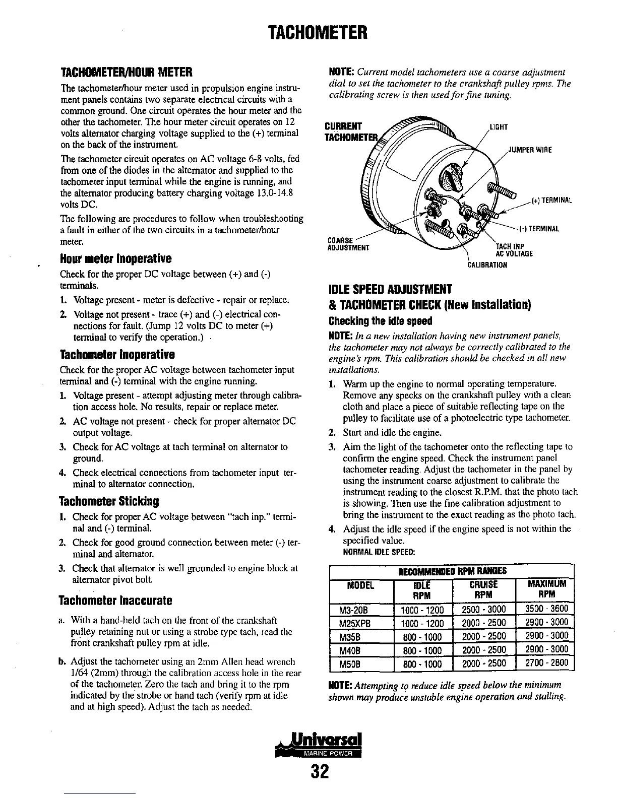
NOTE:
Current model tachometers use a coarse adjustment
dial to set the tachometer to the crankshaft pulley
rpms.
The
calibrating screw is then used
for
fine tuning.
CURRENT
CDARSE
ADJUSTMENT
IDLE
SPEED
ADJUSTMENT
WIRE
TERMINAL
&
TACHOMETER
CHECK
(New
Installation)
Checking
the
idle
speed
NOTE:
In
a new installation having new instrument panels,
the tachometer
may not always be correctly calibrated to
the
engine's rpm. This calibration should be checked in all new
installations.
1.
Wann
up
the
engine
to
nonnal
operating
temperature.
Remove any specks
on
the crankshaft pulley with a clean
cloth and place a piece
of
suitable reflecting tape on the
pulley to facilitate use
of
a photoelectric type tachometer.
2.
Start and idle the engine.
3. Aim the light
of
the tachometer onto the reflecting tape
to
confinn the engine speed. Check the instrument panel
tachometer reading. Adjust the tachometer in the panel
by
using
the
instrument
coarse
adjustment
to
calibrate
the
instrument reading to the closest
R.P.M.
that the photo tach
is showing. Then use the fine calibration adjustment
to
bring the instrument
to
the exact reading as the photo tach.
4.
Adjust the idle speed if the engine speed
is
not within the
specified value.
NORMAL
IDLE
SPEED:
RECOMMEIIIED
RPM
IWIGES
MODEL
IDLE
CRUISE
MAXIMUM
RPM
RPM
RPM
M3-20B
1000
-
1200
2500
-
3000
3500
-
3600
M25XPB
1000
-
1200
2000
-
2500
2900·3000
M35B
800-1000
2000
- 2500
2900
-
3000
M40B
800
-1000
2000
- 2500
2900
-
3000
M50B
800
-
1000
2000·2500
2700
-
2800
NOTE:
Attempting to reduce idle speed below the minimum
shown may produce unstable engine operation and stalling.
32