ENGINE
ADJUSTMENTS
. -
..
~
.
NOTE:
UNIVERSAL recommends
thanhe
following engine
~adjustments
be peiformed by a competent engine mechanic.
The information below is provided to assist the mechanic.
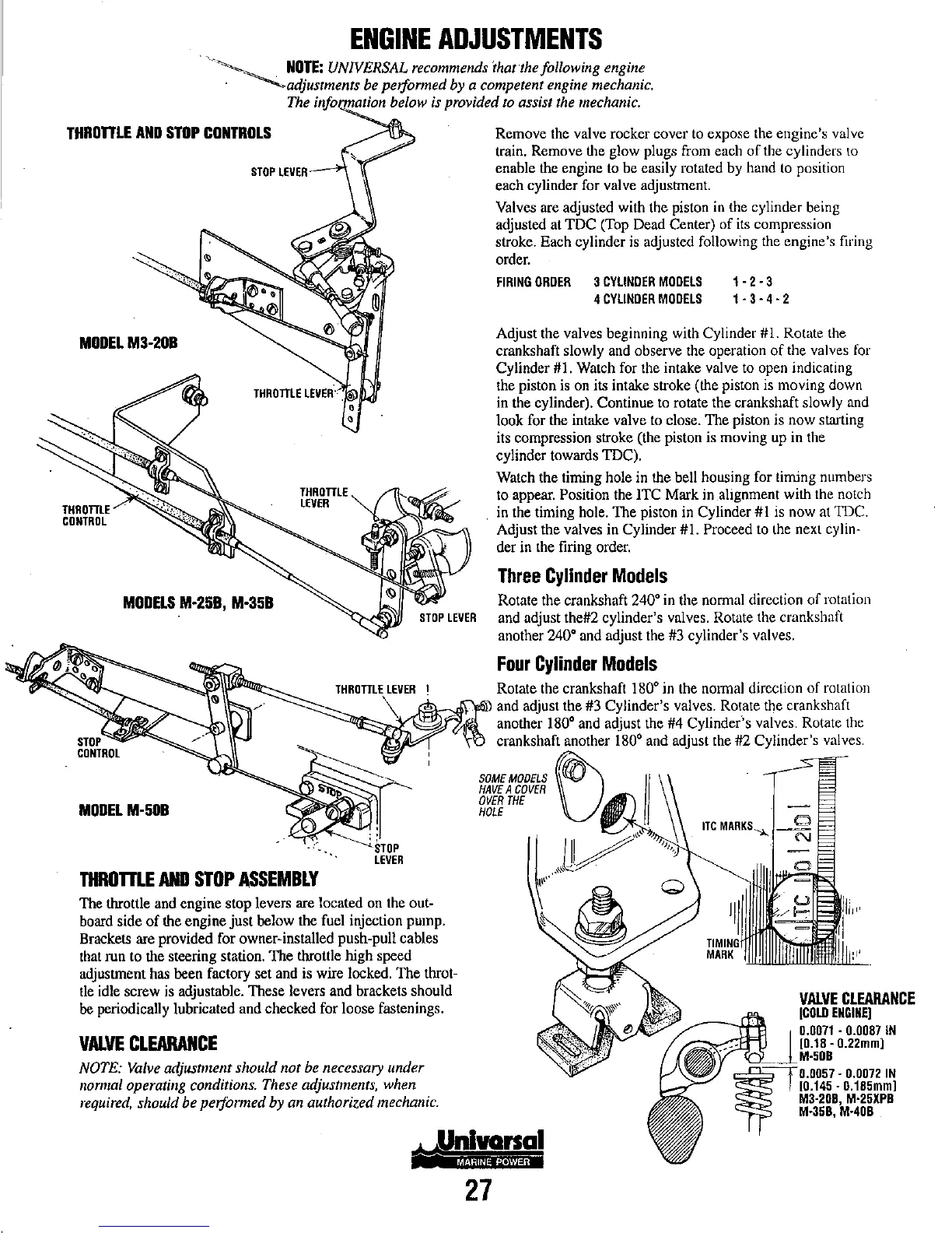
THROnLE
ANO
STOP
CONTROLS
MOOEL
M3-20B
THROTTLE
LEVER'
.
,
•
THROTTLE
CONTROL
MODELS
M-2SB,
M-3SB
MODEL
M-SOB
THROTTLE
LEVER
THROrnE
AND
STOP
ASSEMBLY
The throttle and engine stop levers are located on the out-
board side
of
the engine
just
below the fuel injection pump.
Brackets are provided for owner-installed push-pull cables
that run to the steering station.
The
throttle high speed
adjustment has been factory set and is wire locked.
The
throt-
tle idle screw is adjustable. These levers and brackets should
be periodically lubricated and checked for loose fastenings.
VALVE
CLEARANCE
NOTE:
Valve
adjustment should not be necessary under
normal operating conditions. These adjustments, when
required,
should be peiformed by an authorized mechanic.
Remove the valve rocker cover to expose the engine's valve
train. Remove the glow plugs from each
of
the cylinders
to
enable the engine to be easily rotated by hand
to
position
each cylinder for valve adjustment.
Valves are adjusted with the piston in the cylinder being
adjusted at
TOC
(Top Dead Center)
of
its compression
stroke. Each cylinder is adjusted following the engine's firing
order.
FIRING
OROER
3
CYLINOER
MODELS
4
CYLINDER
MODELS
1-2-3
1·3-4-2
Adjust the valves beginning with Cylinder #1. Rotate the
crankshaft slowly and observe the operation
of
the valves for
Cylinder #1. Watch for the intake valve to open indicating
the piston is on its intake stroke (the piston is moving down
in the cylinder). Continue to rotate the crankshaft slowly and
look for the intake valve to close. The piston is
now
starting
its compression stroke (the piston is moving up in the
cylinder towards TDC).
Watch the timing hole in the bell housing for timing numbers
to appear.
Position the ITC Mark in alignment with the notch
in the timing hole.
The
piston in Cylinder
#1
is now at TOC.
Adjust the valves in Cylinder #1.
Proceed to the next cylin-
der in the firing order.
Three
Cylinder
Models
Rotate the crankshaft
240'
in the normal direction
of
rotation
and adjust the#2 cylinder's valves. Rotate the crankshaft
another
240'
and adjust the #3 cylinder's valves.
Four
Cylinder
ModelS
Rotate the crankshaft
180'
in the nmmal direction
of
rotation
and adjust the #3 Cylinder's valves. Rotate the crankshaft
another
180'
and adjust the #4 Cylinder"s valves. Rotate the
crankshaft another
180'
and adjust the #2 Cylinder'S valves.
SOME
MOOELS
~0
HAVE
A
COVER
OVER
THE
HOLE
27
VALVE
CLEARANCE
(COLO
ENGINE(
0.0071
·0.0087
tN
[0.18
-
0.22mml
M·5DB
,,=,,=.=!=t
0.0057
-
0.0072
IN
10.145
-
0.185mml
M3·20B,
M·25XP8
M-358,
M·40B