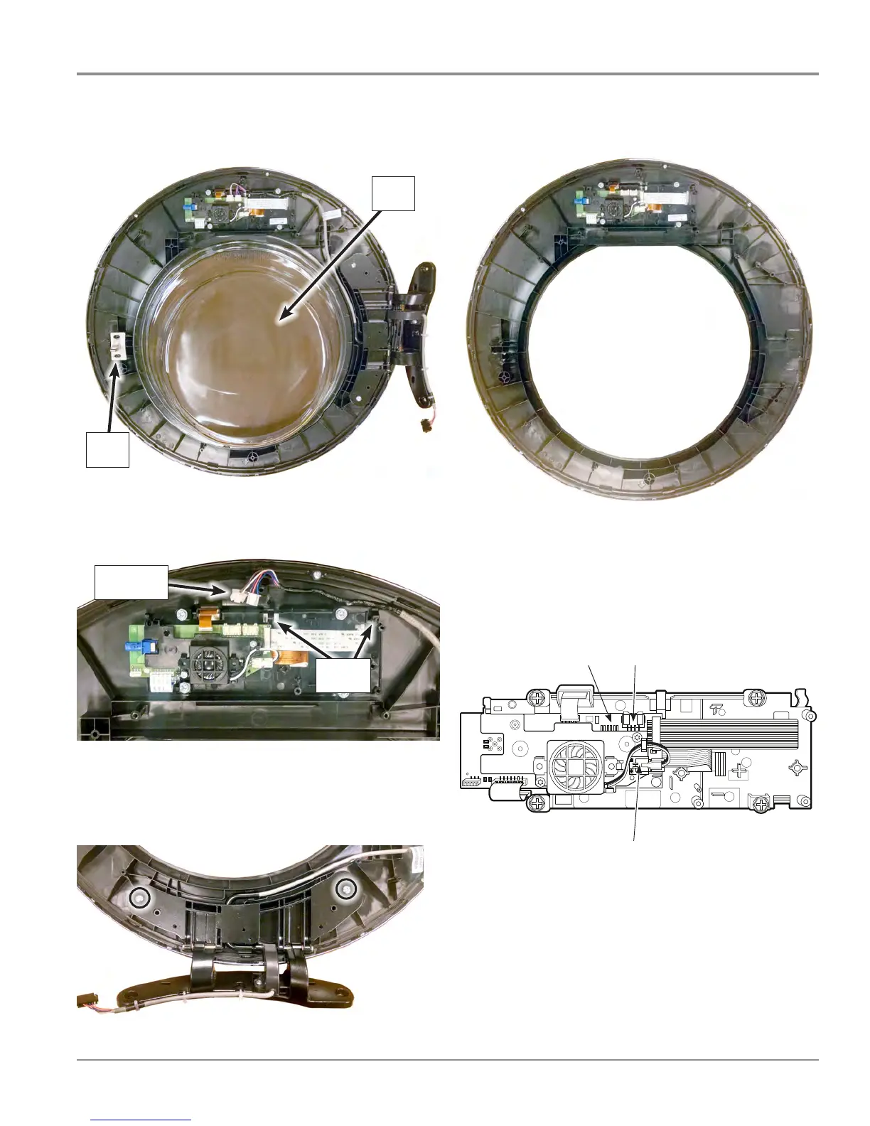
6. Remove the inner door glass and catch. Set aside for
Figure 4).
7. Disconnect the ACU and Drum Light harnesses from the
HMI. Unclip harness from HMI enclosure. See Figure 5.
8. Using a Phillips screwdriver, remove the two (2) screws
9. Reverse procedure to reassembly all parts onto the new
Outer Door/HMI Assembly (see Figure 7).
3$*(
FOR SERVICE TECHNICIAN’S USE ONLY
DO NOT REMOVE OR DESTROY
10. Check HMI input voltage:
Verify that there is 5V between pin 1 and 4
at J16.
¾If there is 5V, go to step 11.
¾If there is not 5V, disconnect J16 and
check for 15V between pin ? and pin ?.
If there is not 15V, replace the ACU.
11. Unplug washer/dryer or disconnect power.
12. Reassemble all parts and panels.
13. Perform the Service Diagnostic Mode
Tests on page 5 to verify repairs.
TEST #2: Human-Machine
Interface (HMI)
This test is performed when any of the
following situations occurs during the
Service Diagnostic Mode Tests (see page 5):
display does not turn on and/or no sound
is heard.
1. Unplug washer or disconnect power.
2. Gently lay washer/dryer on its right side
to access the ACU.
3. Visually check that all ACU connectors are
inserted all the way into the ACU. See Figure 3,
page 10.
4. Visually check that all HMI connectors
are inserted all the way into the HMI.
5. If all visual checks pass, perform TEST #1:
ACU Power Check, page 10, to verify supply
voltage and health of microcontroller.
¾If supply voltages are present and
microcontroller is functioning properly,
replace the HMI and housing assembly.
¾If supply voltages are not present,
replace the ACU.
6. Reassemble all parts and panels.
7. Plug in washer/dryer or reconnect power.
8. Perform the Service Diagnostic Mode
Tests on page 5 to verify repair.
Figure 4 - Human-Machine Interface (HMI) and Housing Assembly
ACU Input
(3 pin
connector)
Speaker
 Loading...