6400 Reference Manual
21
Magnetic Pickup / Optical Sensor
Both of these methods works well to provide a once-per-turn synchronization reference by tracking the
revolution of a reflective reference such as a hole, pin or reflective tape.
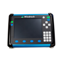
Magnetic Pick-up
• The magnetic pick-up will cause the sync light to flash at the center of the hole or pin target.
• Typically, a pin works better than a hole.
• A ¼ inch target with a ¼ inch gap to the pickup is a good starting point for gapping the magnetic pickup.
• The magnetic pickup uses a standard accelerometer cable that plugs into the TDC plug on the encoder
on the LEMO end and the magnetic pickup on the other end.
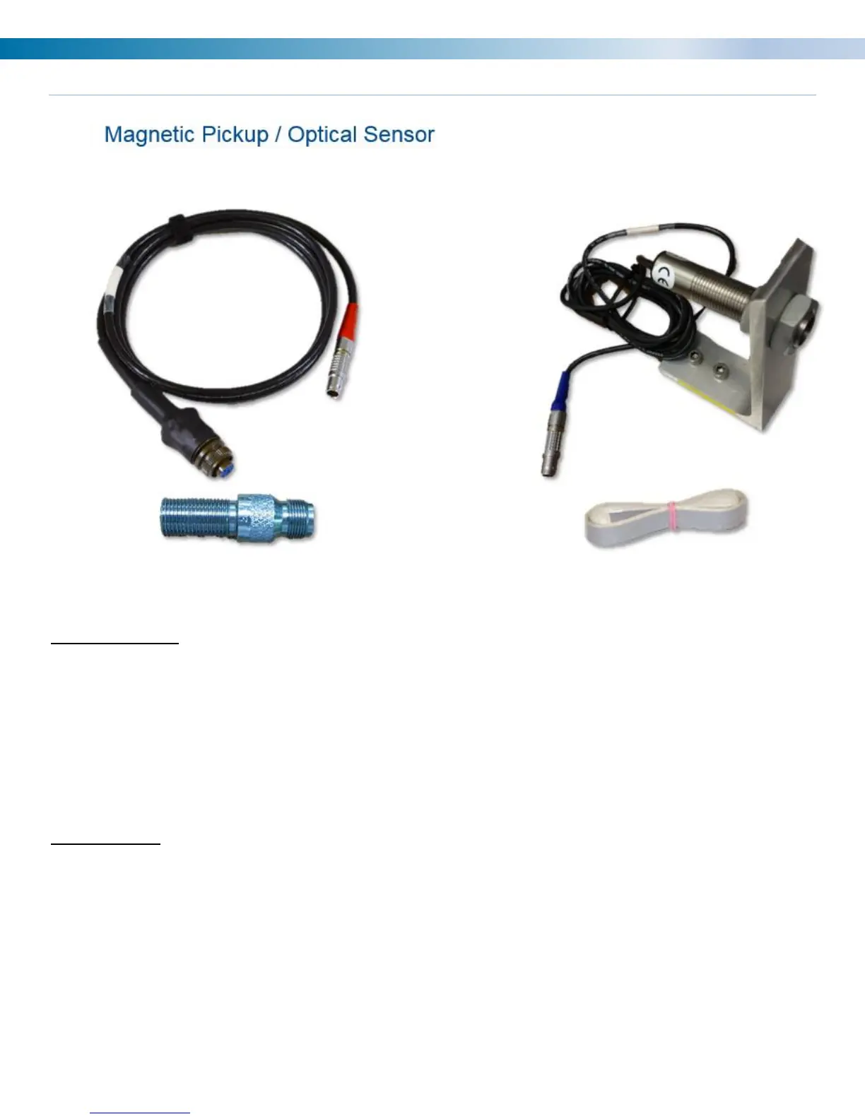
Optical Sensor
• The sync light will flash at the leading edge of the reflective tape.
• Do not place the reflective tape near TDC as the sync light will flash at the same time the optical sensor
will be looking for the signal. This can make it more difficult to sync than it should be.
• Cutting the width of the tape in half can help with getting a reliable speed reference.
• This sensor has trouble if there is bright sunlight.
• A normal starting gap for the optical pickup is about 1-3 inches.
• The optical pickup has an integrated LEMO connector that plugs into the TDC plug on the encoder.