6400 Reference Manual
12
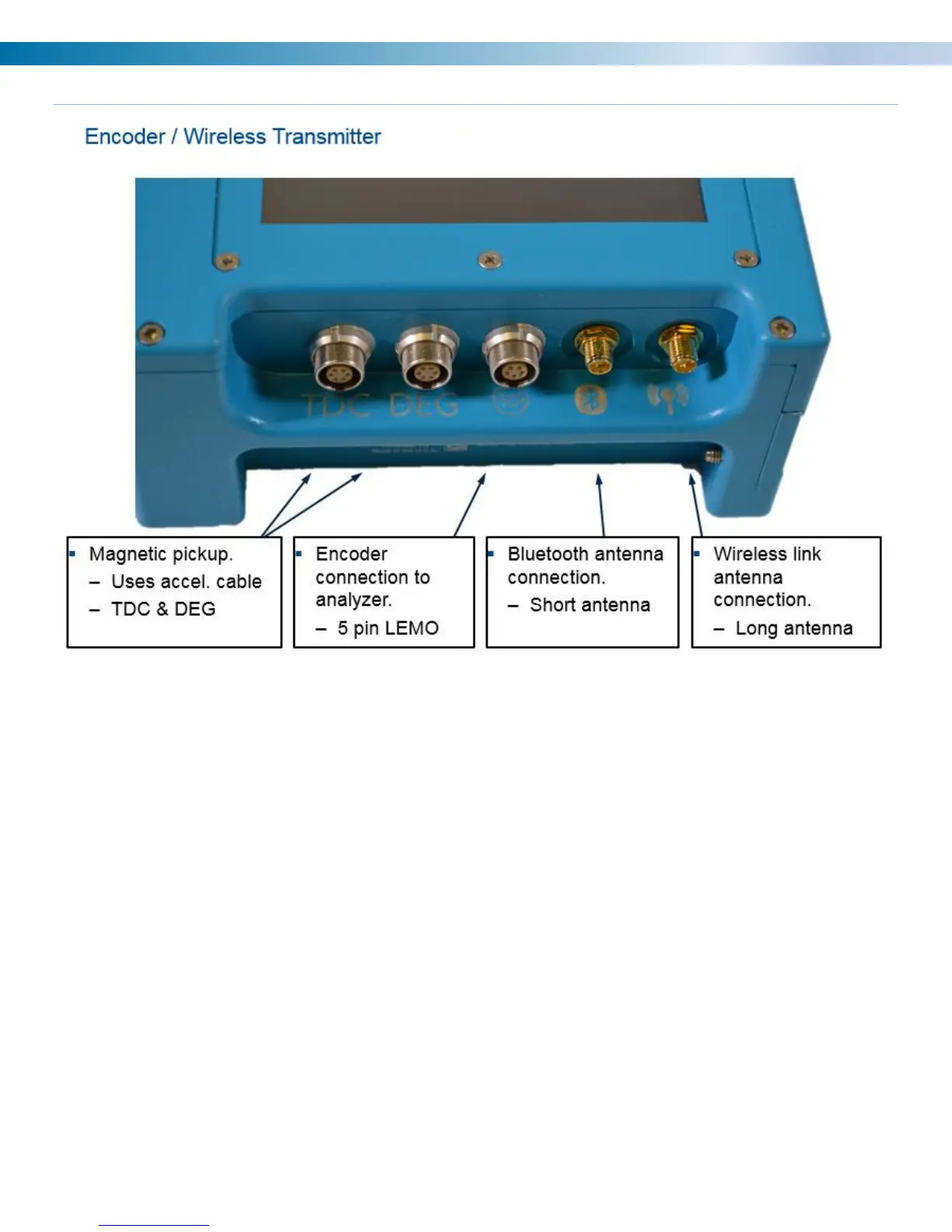
Encoder / Wireless Transmitter
The encoder converts the rotational motion of the crankshaft into electrical signals. The encoder generates a
pulse per degree (PPD) signal and a pulse per revolution (PPR) signal for tracking crankshaft motion. The half
inch shaft is for connecting to a rotating element at running speed.
The analyzer takes the information from the encoder and preprocesses it to match the setup for the unit (2 or 4
stroke, A/B phase shift). This makes the encoder easier to use and the data easier to collect as you don’t need
to go to the encoder to make any changes after the initial setup.
The encoder also incorporates Mag Pickup, Prox. Probe or Optical input connectors for once per turn inputs
(TDC).
The DEG input is an optional input to track the angular velocity between TDC triggers.
The third connector is a 5 pin LEMO for a direct connection to the analyzer with an encoder cable. Cable sold
separately.
Note: The 6320 encoder cable is not compatible with the 6400.
The short antenna is for blue tooth connection that is currently used for firmware updates and is not required
for normal operation.
The long antenna is for sending speed information to the 6400 and is required when using the wireless
function.