Do you have a question about the Windrock 6400 and is the answer not in the manual?
Defines the objectives of using the analyzer for equipment assessment.
Details condition and performance metrics for engine analysis.
Details condition and performance metrics for compressor analysis.
Specifies data collection locations for turbochargers and blowers.
Identifies primary and secondary ignition data collection points.
Describes locations for TDC reference signals.
Specifies points for cylinder exhaust temp and vibration.
Identifies points for cylinder pressure and frame vibration.
Specifies locations for TDC reference signals on compressors.
Identifies points for suction/discharge and valve cap temperatures.
Specifies locations for head/crank and nozzle pressure.
Specifies TDC reference and crosshead vibration points.
Identifies points for rod motion and frame vibration.
Specifies points for valve, ring, and liner vibration.
Specifies TDC reference for ultrasonic measurements.
Identifies points for ultrasonic vibration and liner scoring.
Instructions for removing and installing the analyzer battery.
Instructions for transmitter battery replacement.
Instructions for strobe light battery replacement.
Details the top view of the analyzer and its connectors.
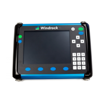
Explains the analyzer's purpose and signal measurement capabilities.
Lists different configurations of the Windrock 6400 analyzer.
Describes the front panel layout and button functions.
Details the bottom panel features and connectors.
Guide to adjusting the analyzer screen's brightness level.
Steps to set the analyzer's date and time.
Introduces the encoder and its wireless capabilities.
Explains how the encoder converts motion to electrical signals.
Details the various input connectors for the encoder.
Description of the encoder's touch screen interface.
Guide to selecting wireless channels and frequencies.
Details the power button and battery level indicator.
Explains different encoder modes like EN, MP, OP, P-, SM.
Procedure for setting Top Dead Center in MP mode.
Guidance on setting the signal threshold for MP mode.
Notes on potential issues and their resolution in MP mode.
Steps to configure for both TDC and degree measurements.
Configuration options for OP mode including TDC and degree.
Guide to setting the threshold level for Prox Negative mode.
Explains how to use the simulator mode and its restrictions.
Provides FCC and Industry Canada compliance information.
Detailed process for choosing the optimal wireless channel.
Guidance on selecting internal or external antennas.
Description and usage of the magnetic pickup sensor.
Description and usage of the optical sensor.
Details on the standard included cables.
Information on available optional cables.
How to use the strobe light for synchronization.
Procedure for setting degree offsets using the strobe.
Details on the engine pressure sensor's range and type.
Instructions for zeroing the sensor and compensating for thermal effects.
Specifications for the compressor pressure sensor.
Guidance on connecting and cleaning the sensor.
Procedure for zeroing the compressor sensor.
How to calibrate pressure transducers before use.
Alternative method for zeroing sensors during data collection.
How to connect and use the primary ignition pick-up.
Information on the measurement range for primary ignition.
Description of the secondary ignition capacitive clip.
Information on the measurement range for secondary ignition.
Critical safety instruction for secondary ignition testing.
How the accelerometer works and where to place it.
Details on sensitivity and proper handling.
How the velocity probe works and its integration capabilities.
Details on sensitivity and proper handling.
Description of the integrated ultrasonic and IR temperature sensor.
Introduction to adjusting the ultrasonic sensor gain.
Step-by-step guide to adjust ultrasonic gain.
Explanation of how gain settings are stored.
Visual examples of trace representations for gain adjustment.
Instructions for connecting headphones.
Steps to initiate free-form data collection.
How to access the audio playback feature.
Guide to adjusting volume and gain for playback.
Specific steps to adjust gain for audio playback.
Details the components included in the VA kit.
| Brand | Windrock |
|---|---|
| Model | 6400 |
| Category | Measuring Instruments |
| Language | English |