6400 Reference Manual
15
Magnetic Pickup (MP) - Uses a magnetic pickup plugged into an accelerometer cable to see a target on the
flywheel. The encoder can automatically determine whether a pin or hole is being detected and polarity of the
sensor wires is not critical so long as both wires have no reference to ground.
Setting TDC (top dead center / once-per-turn)
The threshold adjustment controls the
sensitivity or level detection of the signal. It
defaults to 20 (least sensitivity) and can be
adjusted up or down by slowly rotating the
shaft.
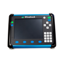
If the signal does not exceed the threshold
level, the device will not show an RPM number
and the threshold number on the gauge is red
as shown.
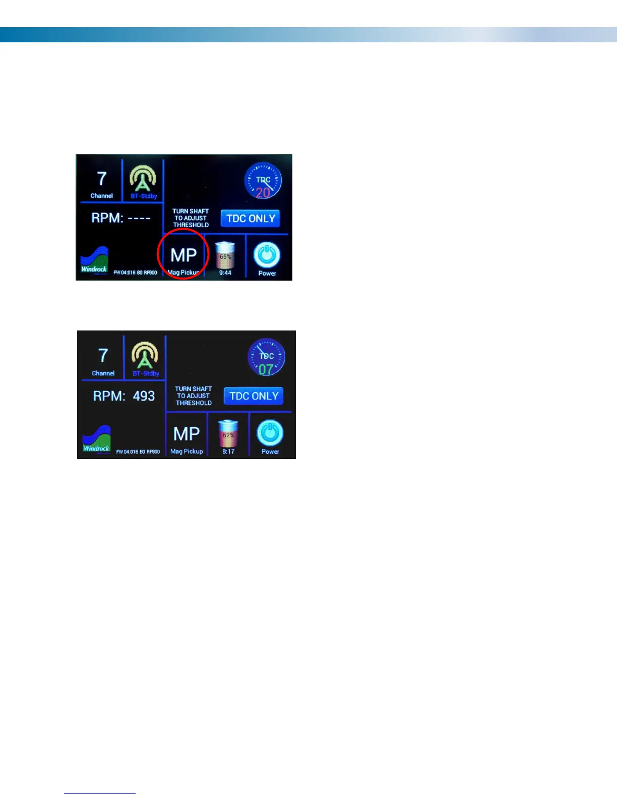
Once the signal level exceeds the threshold
level, the device will calculate an RPM and
display it if the RPM is within measuring range
as shown.
TIPS FOR SETTING THRESHOLD LEVEL
One characteristic of magnetic pickups is that their signal amplitude changes with the speed of the flywheel, ie,
as the speed increases, the signal gets larger, and as the speed decreases, the signal gets smaller. If the
threshold level is lowered from 20 until the tip of the signal is just detected while running at a higher speed, the
threshold setting may not work if the signal gets smaller at a lower speed. Therefore, it is recommended that
the threshold level is swept over the range of the gauge noting the upper and lower bound numbers where the
colors change between green and red and then setting the level halfway between them.
Noise or other artifact considerations
If noise is present or other artifacts such as a previously used pin on the flywheel which has not been
completely ground down, and the threshold number is set to a level that detects them, the RPM number can
become erratic or indicate a multiple of the correct rpm. For example, if a ground down pin was detected while
the engine/compressor was running at 300 rpm, the encoder would see a stable 600 rpm and the gauge
number would be green, therefore, the lower bound gauge number to reference would not be a red/green color
change but change to an incorrect rpm.