3064810_201804 29
15. Electrical connection
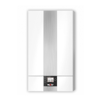
Connection,Z1output(230VAC;max.1.5A)*
Insert and secure the power cable through the cable gland.
Connect the power cable to terminals L1, N and
.
* Max. 1.5 A/345 VA per output, sum of all outputs no
more than 600 VA
Fig: Connection of Z1 output
Netz
N
L1
Z1
N
L1
A1
N
L1
ZHP
N
L1
L1
LP
N
SF
1
2
AF
E1
eBUS
+
-
1
2
a
b
E2
a
b
1 2
1 2
1 2
1 2
1 2
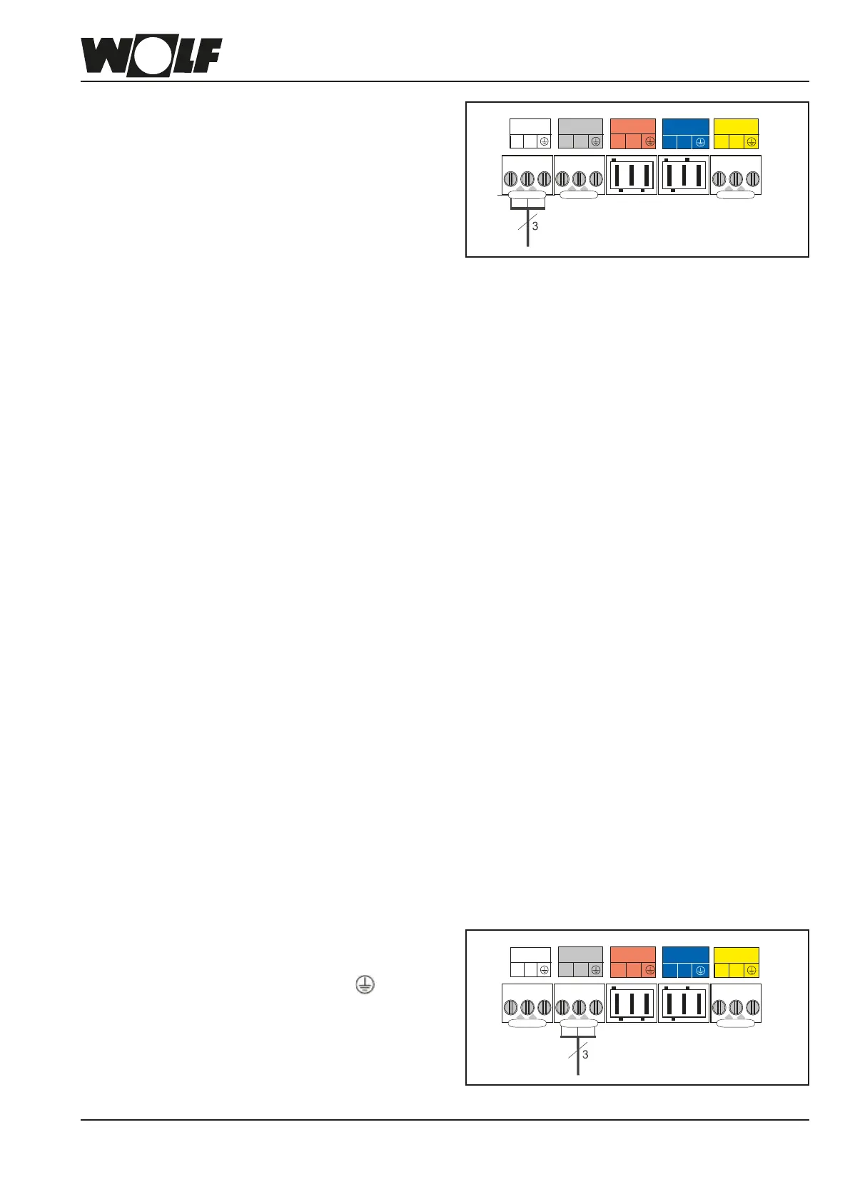
230Vmainsconnection
The control and safety equipment is fully wired and tested.
You only need to connect the power supply and the external
accessories.
Create a permanent connection for the power supply.
Provide the power supply via a mains isolator (e.g. heating
system emergency stop switch) that ensures at least 3 mm
contact separation for all poles.
No other consumers may be connected to the power cable.
The appliance (IP rating IPX4D) is approved for installation
in the immediate vicinity of a bath or shower (protected area
1 according to DIN VDE 0100). Measures must be taken to
prevent jets of water.
In rooms with a bathtub or shower, the appliance may be
connected only via an RCD.
Installationinformation,electricalconnection
- Isolate the system from the power supply before opening.
- Check that the appliance is isolated from the power supply.
- Swivel the control unit cover to one side.
- Remove the front casing.
- Open the lower casing cover of the HCM-2.
- Flexible power cable, at least 3x1.0 mm
2
(strip approx.
70 mm of insulation)
- Remove the insert from the HCM-2 casing.
- Push the cable through the strain relief (insert) and secure.
- Pull out the Rast5 plug.
- Terminate the appropriate cores at the Rast5 plug.
- Push the inserts back into the HCM-2 casing.
- Push the Rast5 plugs back into their correct positions.
Fig: Mains connection
Netz
N
L1
Z1
N
L1
A1
N
L1
ZHP
N
L1
L1
LP
N
SF
1
2
AF
E1
eBUS
+
-
1
2
a
b
E2
a
b
1 2
1 2
1 2
1 2
1 2
 Loading...