30 3064810_201804
15. Electrical connection
When installing the appliance in places where
there is a risk of increased electromagnetic
interference,itisadvisabletotscreened
sensor leads and eBus cables. One end of
the cable shield should be connected to the
PE potential in the control unit.
Please
note
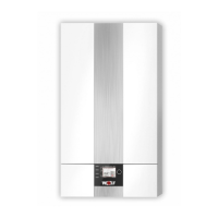
ConnectingoutputA1(230VAC;max.1.5A)*
Insert and secure the power cable through the cable gland.
Connect the power cable to terminals L1, N and
.
The parameters for output A1 are described in the table.
* Max. 1.5 A/345 VA per output, sum of all outputs no more
than 600 VA
Fig: Connection of A1 output
Netz
N
L1
Z1
N
L1
A1
N
L1
ZHP
N
L1
L1
LP
N
SF
1
2
AF
E1
eBUS
+
-
1
2
a
b
E2
a
b
1 2
1 2
1 2
1 2
1 2
ConnectinginputE1
Insert and secure the power cable through the cable gland.
Connect the connection cable for input E1 to terminals E1 as
shown in the wiring diagram.
No external voltage may be connected to in-
put E1, as this could destroy the component.
Please
note
Fig: Connection of E1 output
Netz
N
L1
Z1
N
L1
A1
N
L1
ZHP
N
L1
L1
LP
N
SF
1
2
AF
E1
eBUS
+
-
1
2
a
b
E2
a
b
1 2
1 2
1 2
1 2
1 2
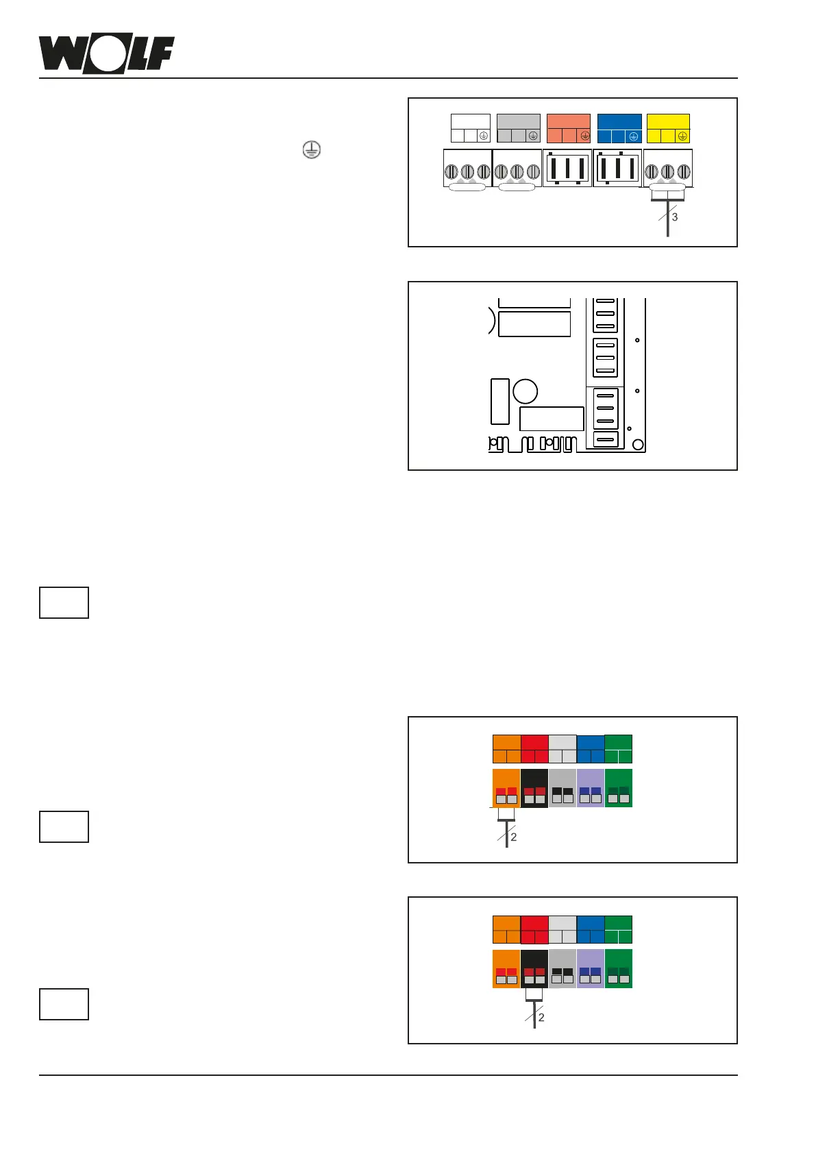
Connectinglowvoltagedevices
ConnectinginputE2
Insert and secure the power cable through the cable gland.
Connect the connection cable for input E2 to terminals E2 as
shown in the wiring diagram.
Only one external voltage of up to 10 V
can be connected to input E2, oth-
erwise the PCB will be destroyed.
1(a) = 10 V, 2(b) = GND
Please
note
Fig: Connection of E2 input
Netz
N
L1
Z1
N
L1
A1
N
L1
ZHP
N
L1
L1
LP
N
SF
1
2
AF
E1
eBUS
+
-
1
2
a
b
E2
a
b
1 2
1 2
1 2
1 2
1 2
Fig: Changing a fuse
Changingafuse
Isolate the combi boiler from the power supply prior to chang-
ing a fuse.
The ON/OFF switch on the boiler does not provide isolation
from the power supply.
The F1 and F2 fuses are located under the top casing cover
of the HCM-2.
F1: Fine wire fuse (5x20 mm) 4 A (medium)
F2: Micro fuse 1.25 A (slow)
Danger from live electrical components Never touch electrical
components or contacts if the condensing boiler has not been
isolated from the power supply. Danger to life!
F1
F2
 Loading...