3064810_201804 31
15. Electrical connection
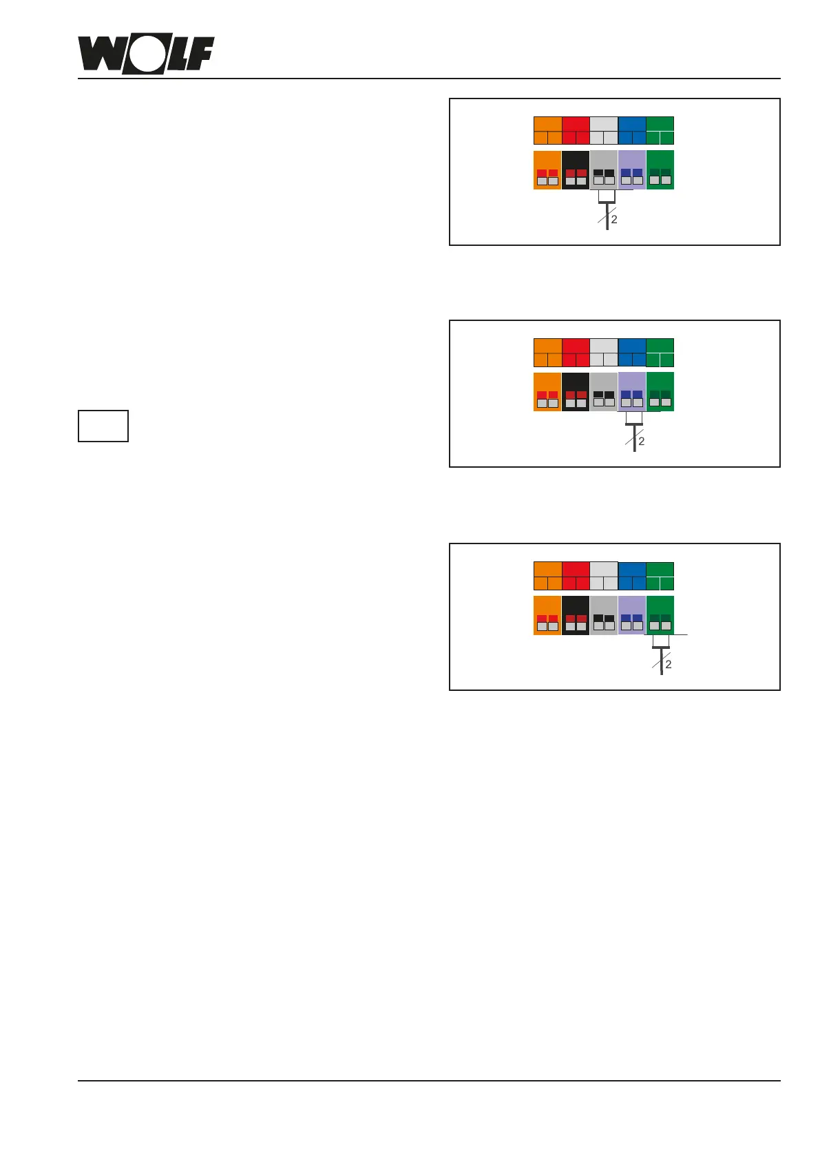
Cylindersensorconnection
Insert and secure the connecting cable through the cable gland.
Connect the cable for cylinder sensor (SF) to the SF terminals
as shown in the wiring diagram.
Use the cylinder sensor from the WOLF con-
trol accessories!
Please
note
ConnectingdigitalWOLFcontrolaccessories
(e.g.BM-2,MM-2,KM-2,SM1-2,SM2-2)
Only control units from the Wolf range of accessories may be
connected. Each accessory is supplied with its own connection
diagram.
Use a two-core cable (cross-section > 0.5 mm²) as the con-
necting cable between the control unit accessory and the
condensing boiler.
Fig: Cylinder sensor connection
Netz
N
L1
Z1
N
L1
A1
N
L1
ZHP
N
L1
L1
LP
N
SF
1
2
AF
E1
eBUS
+
-
1
2
a
b
E2
a
b
1 2
1 2
1 2
1 2
1 2
Fig: Connection of digital Wolf control accessories
(eBUS interface)
Netz
N
L1
Z1
N
L1
A1
N
L1
ZHP
N
L1
L1
LP
N
SF
1
2
AF
E1
eBUS
+
-
1
2
a
b
E2
a
b
1 2
1 2
1 2
1 2
1 2
Connectingoutsidesensor
The outside sensor can be connected to the terminal strip of
the condensing boiler at connection AF, or to the terminal strip
of the BM-2 programming unit.
Fig: Connection of outside sensor
Netz
N
L1
Z1
N
L1
A1
N
L1
ZHP
N
L1
L1
LP
N
SF
1
2
AF
E1
eBUS
+
-
1
2
a
b
E2
a
b
1 2
1 2
1 2
1 2
1 2
 Loading...