30 3062555_201804
15.ConversiontoLPGP(G31)(ifnecessary)
RemovethefourSW8screwsatthegasconnectiontting
andremovethettingfromthegascombinationvalve.
Remove the gas combination valve and gas restrictor.
Place the protective labels at the valve inlet and valve
outlet of the new gas combination valve at the apertures
of the removed valve.
4)
Undo the gas combination valve from the mixing chamber
for gas/air (four SW8 screws).
4 x screws
SW8
3)
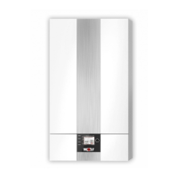
Unscrew the mixing chamber from the fan (three Allen
screws 5 mm), and remove air inlet pipe if necessary
7)
6)
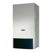
Push the O-ring, lubricated with silicone grease, into the
packinggrooveofthefanandtthemixingchamberwith
the gas combination valve to the burner fan.
Tightengasconnectionttingtogassupplyline.
O-ring
Gas combina-
tion valve
Gas connection
tting
O-ring 23.47 x 2.62
Gas restrictor 6.7
Gas combina-
tion valve
Gas restrictor
5)
4 x SW8 screw
Gas connection
tting
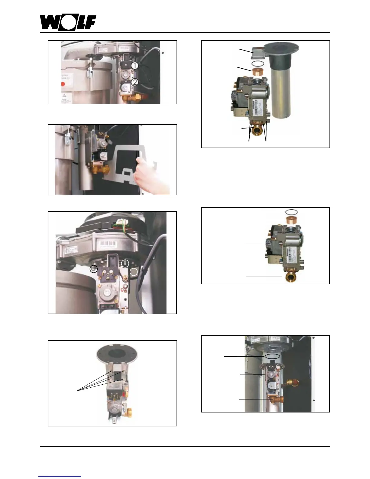
Unplug the connector (rstunscrewthePhillipshead
screws)
1)
Undo gas connection at the gas combination valve
2)
Mixing cham-
ber
ScrewthegasconnectionttingwithO-ring26x4tothe
new LPG gas combination valve.
Insert the new 6.7 gas restrictor into the gas combination
valve.
Use screws to secure the gas combination valve with O-ring
23.4 x 2.6 to the mixing chamber.
Threadedtting
Gas connection