xv
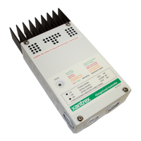
Figure 1-1 C-Series Multifunction DC Charge Controllers - - - - - - 2
Figure 1-2 3-stage Battery Charging Process - - - - - - - - - - - - - - - 5
Figure 1-3 PV Charge Controller - - - - - - - - - - - - - - - - - - - - - - - 7
Figure 1-4 Diversion Controller - - - - - - - - - - - - - - - - - - - - - - - - 9
Figure 1-5 Load Controller - - - - - - - - - - - - - - - - - - - - - - - - - - 11
Figure 1-6 Decal Displaying Load Control Voltage Settings - - - - 12
Figure 1-7 Optional Accessories - CM/R, CM, and BTS- - - - - - - 12
Figure 2-1 Removing the Front Cover - - - - - - - - - - - - - - - - - - - 14
Figure 2-2 C-Series Dimensions and Knockout Locations
(Not to Scale)- - - - - - - - - - - - - - - - - - - - - - - - - - - - 15
Figure 2-3 Mounting the C-Series Multifunction DC Controller - 17
Figure 2-4 Jumper Positions- - - - - - - - - - - - - - - - - - - - - - - - - - 18
Figure 2-5 Circuit Board Components - - - - - - - - - - - - - - - - - - - 19
Figure 2-6 Mode of Operation Jumper- - - - - - - - - - - - - - - - - - - 20
Figure 2-7 Voltage Selection Jumper- - - - - - - - - - - - - - - - - - - - 20
Figure 2-8 EQ/LVR Jumper and Reset Switch - - - - - - - - - - - - - 21
Figure 2-9 Bulk and Float Charge Potentiometers (pots)- - - - - - - 22
Figure 2-10 Bulk and Float Charge Settings for Charge/Diversion
Control Mode- - - - - - - - - - - - - - - - - - - - - - - - - - - - 23
Figure 2-11 Potentiometers with Decal for LVR and LVD Settings 24
Figure 2-12 LVR and LVD Settings for Load Control Mode- - - - - 25
Figure 2-13 R46 Resistor Location - - - - - - - - - - - - - - - - - - - - - - 26
Figure 2-14 Voltage Settings with R46 Resistor Clipped - - - - - - - 27
Figure 2-15 Test Points for Adjusting Voltage Using a DVM - - - - 29
Figure 2-16 Manual Equalization Settings - - - - - - - - - - - - - - - - - 30
Figure 2-17 Front Panel LED and Reset Switch Location- - - - - - - 31
Figure 2-18 Auto Equalization Settings - - - - - - - - - - - - - - - - - - - 32
Figure 2-19 Terminating the Equalization Charge - - - - - - - - - - - - 33
Figure 2-20 Grounding the C-Series Chassis - - - - - - - - - - - - - - - 37
Figure 2-21 DC Connection Terminals - - - - - - - - - - - - - - - - - - - 39
Figures

 Loading...