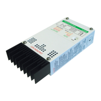
Configuring the C-Series Controller
975-0004-01-02 Rev D 19
Table 2-1
Factory Default Settings for C-Series Controllers
Setting C35, C40 and C60
Battery Voltage 12 volts DC
Equalize/LVR Manual Equalization
Operating Mode Charge Control
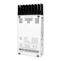
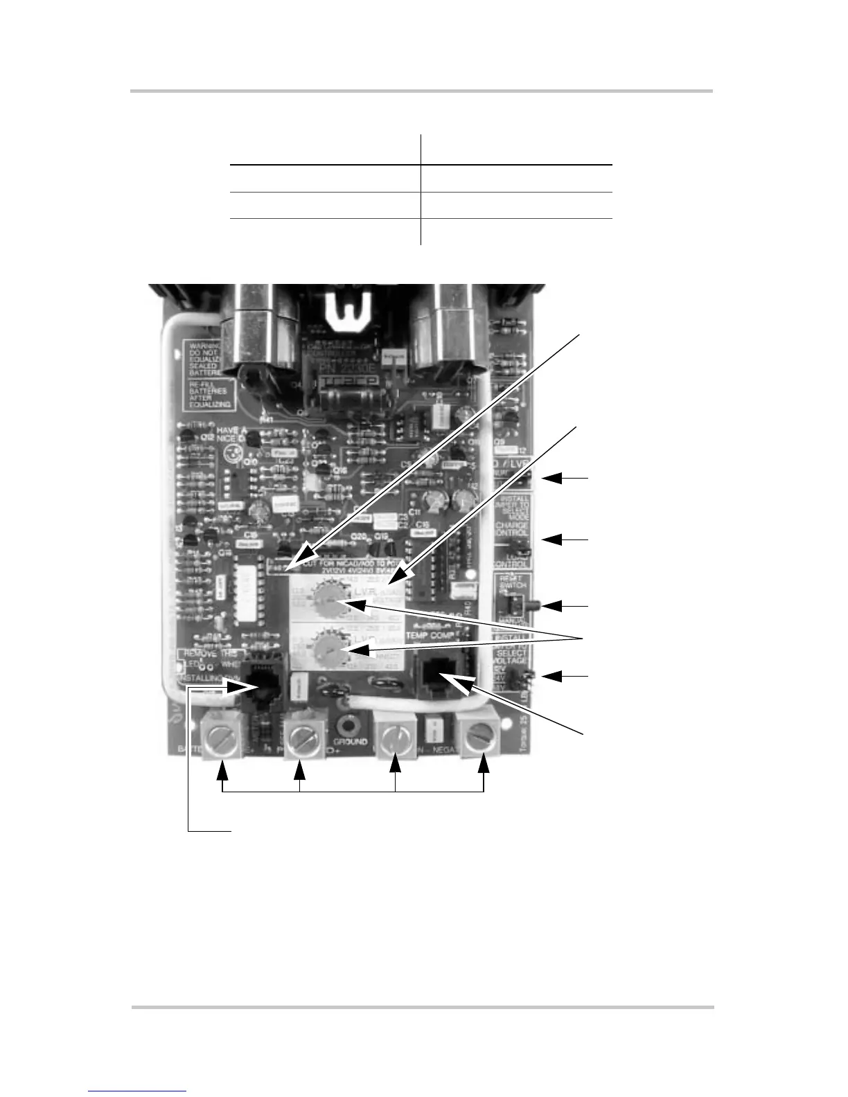
Figure 2-5
Circuit Board Components
Operating
Mode Jumper
Reset Switch
Voltage Jumpe
EQ/LVR
Jumper
DC Terminal Connectors
Potentiometers
Battery
Temperature
Sensor Port
NiCad Setting
Selection R46
Resistor
CM or CM/R Port
Note: This photograph shows the Load Control Voltage decal installed on the
circuit board over the potentiometers.
Load Control
Decal
 Loading...