Installation
2–12 975-0209-01-01
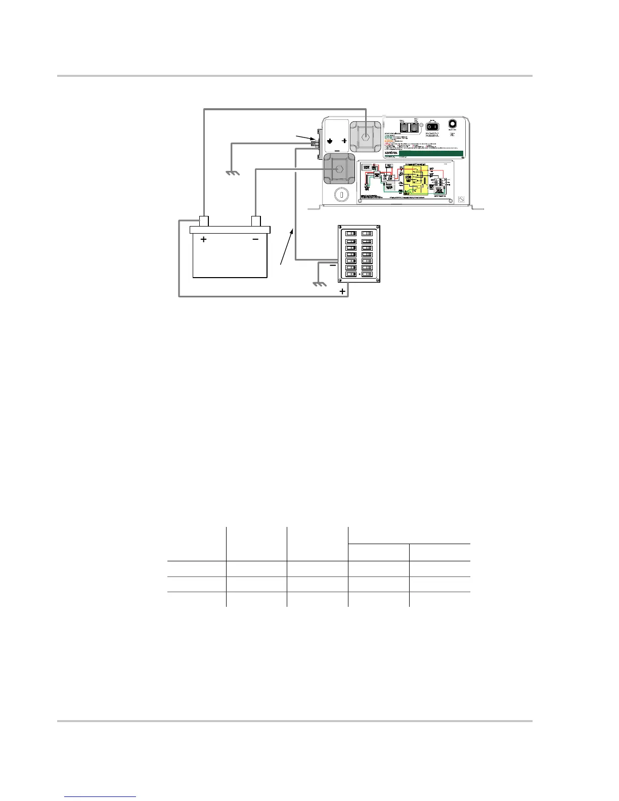
Connect DC loads to Vehicle Chassis or optionally to the Inverter’s Vehicle Chassis
Ground Terminal (Green). The optional connection shown in Figure 2-4 is for
ungrounded DC load distribution panels. Do not connect DC loads to battery
negative (–).
Battery Cable Sizing
The bigger the battery cables, the better. Undersized cables result in additional
stress on the inverter, lower efficiency, reduced surge power, and lower peak
output voltage. Don’t use cables that are too small in diameter because they can
degrade the RV Series Inverter/Charger’s efficiency or generate enough heat to
become a fire hazard. The following table gives recommended cable sizes for
various cable run lengths and inverter voltages.
The U.S. NEC requires that the cables be protected by a fuse or breaker rated to
match the cables’ ampacity at 90 °C.
Figure 2-4
RV Series Grounding Diagram
30
CAUTION
BATTERY POLARITY MUST BE
CORRECT OR DAMAGE WILL
RESULT
VEHICLE
CHASSIS
GROUND
BATTERY
POSITIVE
BATTERY
NEGATIVE
60A
30A
House Battery
RV Series Inverter
DC Load Distribution Panel
Optional
connection
Vehicle chassis ground (green)
Table 2-2
Minimum Recommended Battery Cable Size (In Free Air)
Model
Typical
Amps
Maximum
Fuse Size
Individual Cable length
Under 5 ft 5 to 10 ft
RV2012GS 200 amps 250 A 00 0000
RV2512GS 250 amps 350 A 0000 0000
RV3012GS 300 amps 400 A 0000 0000
 Loading...