Wiring to a Generator
975-0209-01-01 2–19
Auto Gen Start connections
The connections between the inverter/charger and the generator are made on the terminal
strip. All these components are located inside the AC compartment of the inverter. See
Figure 2-8.
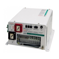
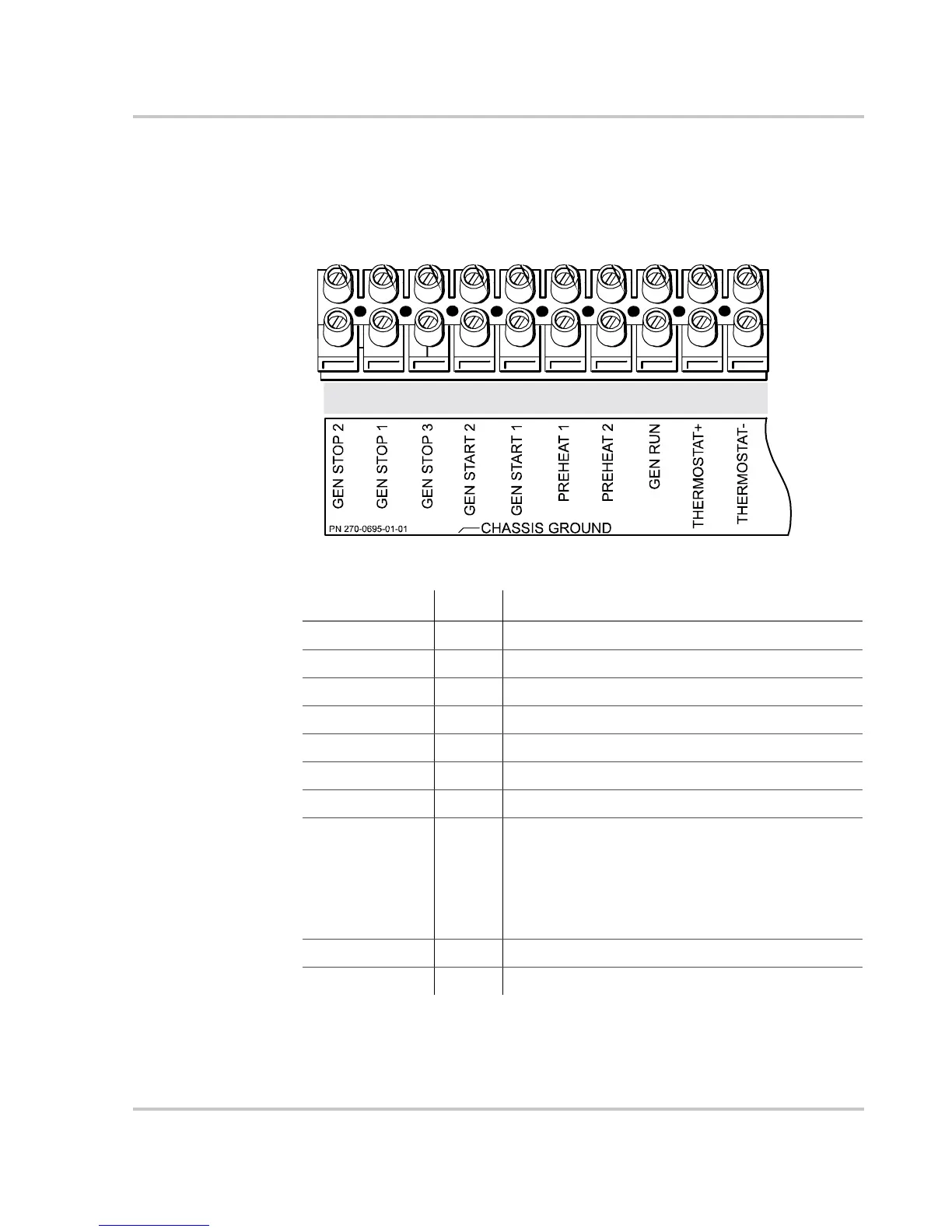
Figure 2-8
RV Series Auto Gen Start terminal block
Terminal Name Relay Description
GEN STOP 2 Relay 1 normally open contact
GEN STOP 1 Relay 1 common contact
GEN STOP 3 Relay 1 normally closed contact
GEN START 2 Relay 2 normally open contact
GEN START 1 Relay 2 common contact
PREHEAT 1 Relay 3 normally open contact
PREHEAT 2 Relay 3 common contact
GEN RUN n/a Generator run signal input. This connection is required
for the inverter/charger to be able to detect when the
generator is running. For example, Power Tech supplies
a gray wire marked “12V power or +12V with engine
running.” This gray wire must connect to the GEN
RUN input.
THERMOSTAT + n/a Thermostat 5V–30V input.
THERMOSTAT – n/a Thermostat return (ground)
 Loading...