Installation
2–20 975-0209-01-01
Relay
timing
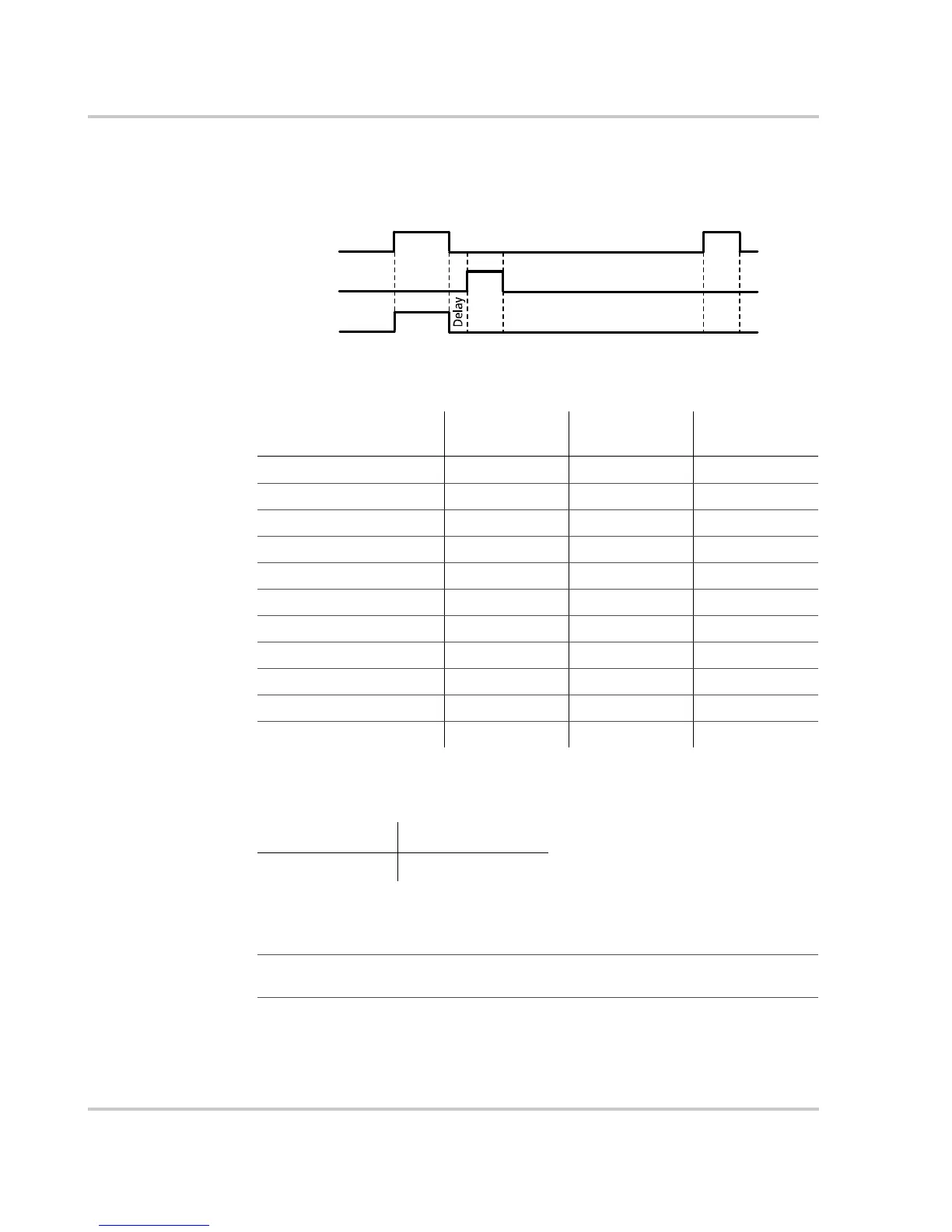
This diagram shows the activity of each internal relay during a generator start sequence.
Wiring size You need #16 or #18 AWG wire to make generator connections. The wire gauge depends
on the distance between the RV Series Inverter/Charger and the generator.
Circuit
protection
Figure 2-9
Relay activity during a start sequence
Table 2-3
Stop/Stop Sequence Timing
Onan
configuration
Power Tech
configuration
Generac
configuration
B+ Hold Time
2 seconds 15 seconds 2 seconds
Preheat Time
15 7 25
Preheat to Crank Delay
210
Crank Time
25 15 15
Crank Retry Time
30 15 15
Spindown Time
333
Stop Pulse Time
60 9 60
Post Stop Pulse Wait Time
050
Max Stop Tries
141
Starter Cooldown Time
60 120 30
Max Start Tries
333
Stop
Run
Start
Time
Preheat
Relay1: Glow/Stop
Relay2: Start (Cranking)
Relay3: Preheat (Glow)
Crank
Preheat/
Stop
0 to 30 ft. (9 m) Over 30 ft. (9 m)
18 AWG 16 AWG
Important:
All circuits (except for ground connections) connecting to the Auto Gen
Control relays must be protected with fuses rated at 5 amps or less.
 Loading...