July 2019
4-34
Xerox® B205/B215 Multifunction Printer Service Manual
REP 4.9
Initial Release
Repairs / Adjustments
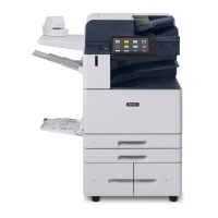
25. Remove the Registration Roll from the Paper Path Frame, Figure 18.
NOTE: Note the location of the bushing in the frame for reinstallation.
Figure 18 Registration Roll Removal
26. Remove the bushing and e-ring from the Registration Roll, Fi
gure 19.
Figure 19 Registration Roll
Replacement
NOTE: Tapered plastic screws and round machine screws are used to hold the parts to the
frame. make sure that the plastic screws go into plastic components and machine screws go
into the metal frame.
The replacement is the reverse of the removal procedure.
NOTE: The frame is flexible and can be bowed out if the screws are not tightened in the cor-
rect order. Reinstall the frame as follows so it seat
s flush against the printer’s internal modules.
1. After aligning the left and right frames together with the inside modules; install, but do not
t
ighten, the three Paper Path Frame screws on the Right, Figure 14, and three Left, Fi
gure
15.
2. On the bottom of the printer, refer to, Figure 8:
a. Install the ground screw.
b. Connect the Printer Drive Motor Connector.
3. Tighten the Paper Path Frame screws installed in Step 1.
4. Continue with the parts replacement:
a. When installing the Paper Feed Sensor Actuat
or make sure the spring is seated in
t
he frame cutout, refer to, Figure 7
.
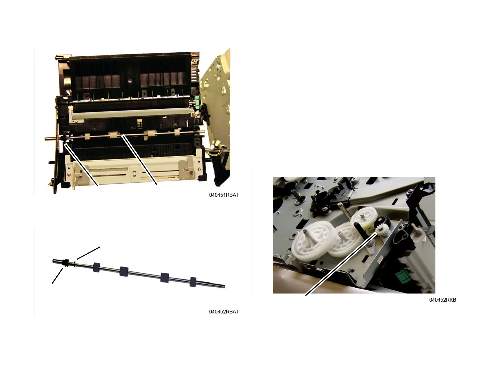
b. Refer to, Figure 20, for installation of the Feed and Registration Drive Gears and
Snap Ring.
Figure 20 Feed and Registration Drive Gears

 Loading...