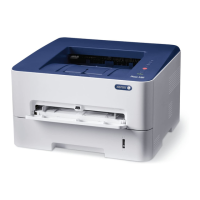
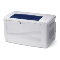
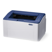
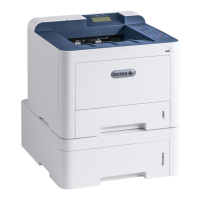
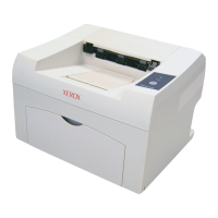
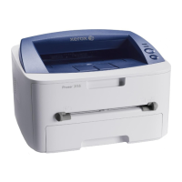
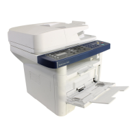
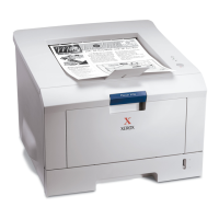
Xerox® Phaser® 3052/3260 Printer
BLOCK SCHEMATIC DIAGRAMS
June, 2014
TABLE OF CONTENTS
This document contains wiring and mechanical power data for the Xerox® Phaser® 3052/3260 Printers. These
block schematic diagrams are supplemental to the diagnostic and troubleshooting information found in the
Xerox Phaser 3025/3260 Family Service Manual.
Every effort has been made to achieve accuracy on these schematics. However, if a difference is noted
between these schematics and the Xerox Service Documentation, the Service Documentation takes
precedence.
CHAIN 1 POWER
1.1 AC / LOW VOLTAGE And HIGH VOLTAGE POWER /
INTERLOCKS
CHAIN 3 COMMUNICATIONS
3.1A PRINTER COMMUNICATION
3.1B PRINTER COMMUNICATION
CHAIN 4 MAIN DRIVE
4.1 MAIN DRIVE
CHAIN 6 LSU
6.1 LSU
CHAIN 7 PAPER FEED AND REGISTRATION
7.1 PAPER FEED AND REGISTRATION
CHAIN 9 XEROGRAPHICS
9.1 PRINT MODULE
CHAIN 10 FUSING AND PRINT EXIT
10.1 FUSING
10.2 PRINT EXIT
Prepared by:
Content Development and Language Services - North America
Xerox Corporation
800 Phillips Road; Building 0218-01A
Webster, New York 14580 USA
©2014 Xerox Corporation. All rights reserved. Xerox® and the sphere of connectivity design are
trademarks of Xerox Corporation in the US and/or other countries..
 Loading...
