June 2014
4-46
Xerox® Phaser® 3052/3260 Service Manual
REP 1.26
Repairs
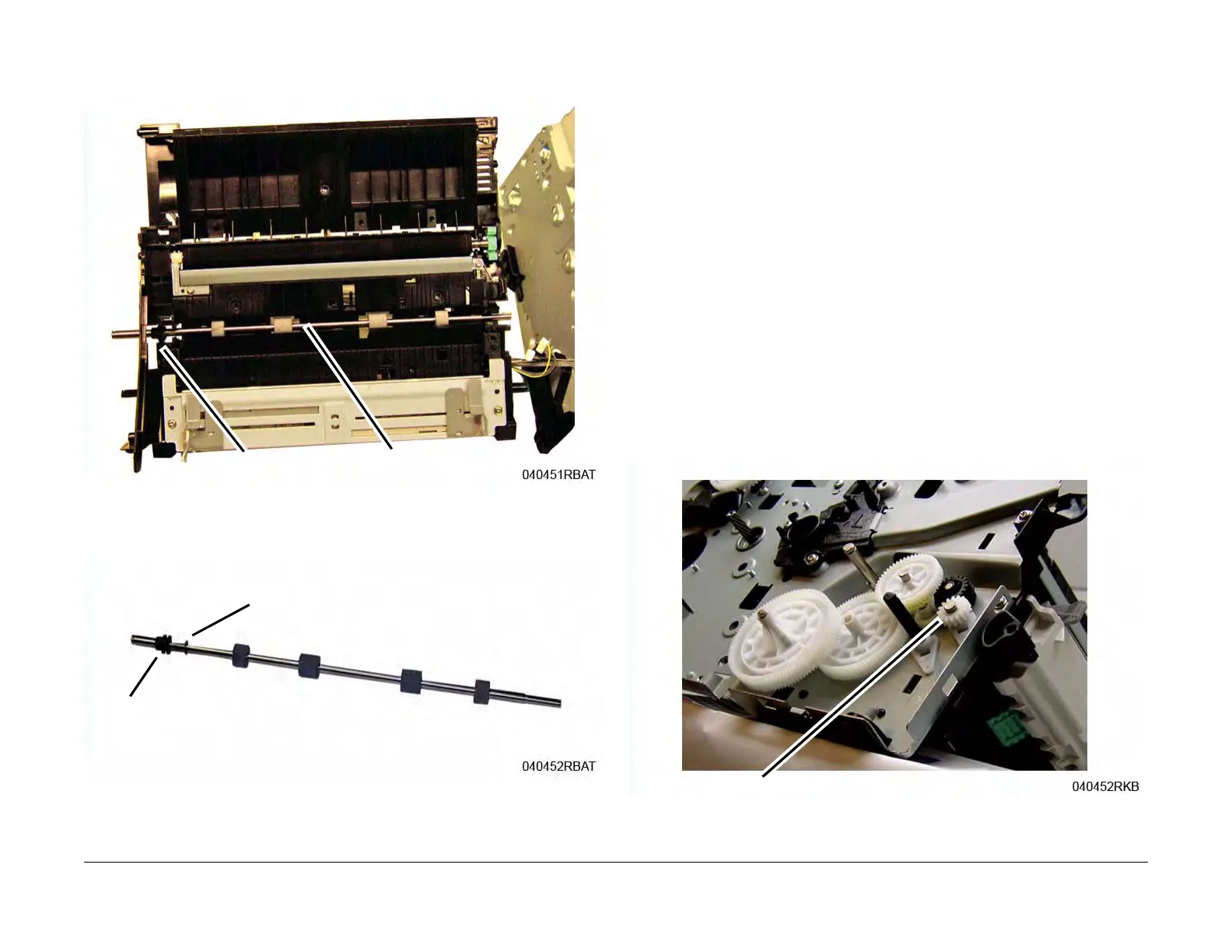
21. Remove the Reg Roll from the Paper Path Frame (Figure 18).
Note the location of the Bushing in the frame for reinstallation.
Figure 18 Registration Roll Removal
22. Remove the Bushing and E-ring from the Reg Roll (Figure 19).
Figure 19 Registration Roll
Replacement
NOTE: Tapered Plastic Screws and Round Machine Screws are used to hold the parts to the
frame. Make sure that the Plastic Screws go into plastic components and Machine Screws go
into the metal frame.
Install the components in the reverse of removal.
NOTE: The Frame is flexible and can be bowed out if the screws are not tightened in the cor-
rect order.
Reinstall the Frame as follows so it seats flush against the printer internal modules.
1. After aligning the left and right frames together with the inside modules; install, but do not
tighten, the Paper Path Frame screws, (3) on the Left and Right Side Frame to hold the
printer together.
Refer to (Figure 14) and (Figure 15).
2. On the bottom of the printer, refer to (Figure 8):
a. Install the ground screw (1).
b. Connect the Printer Drive Motor Connector.
3. Tighten the Paper Path Frame screws installed in Step 1.
4. Continue with the parts replacement.
a. When installing the Paper Feed Sensor Actuator made sure the spring is seated in
the frame cutout, refer to (Figure 7).
b. When installing the Feed and Registration Drive Gears, and Snap Ring, refer to (Fig-
ure 20) for correct installation the Feed and Registration Drive Gears.
Figure 20 Feed and Registration Drive Gears
Registration Roll
Bushing
Bushing
E-ring
Snap Ring