DP224/6 Operators Manual Page 11
Rear Panel Connections
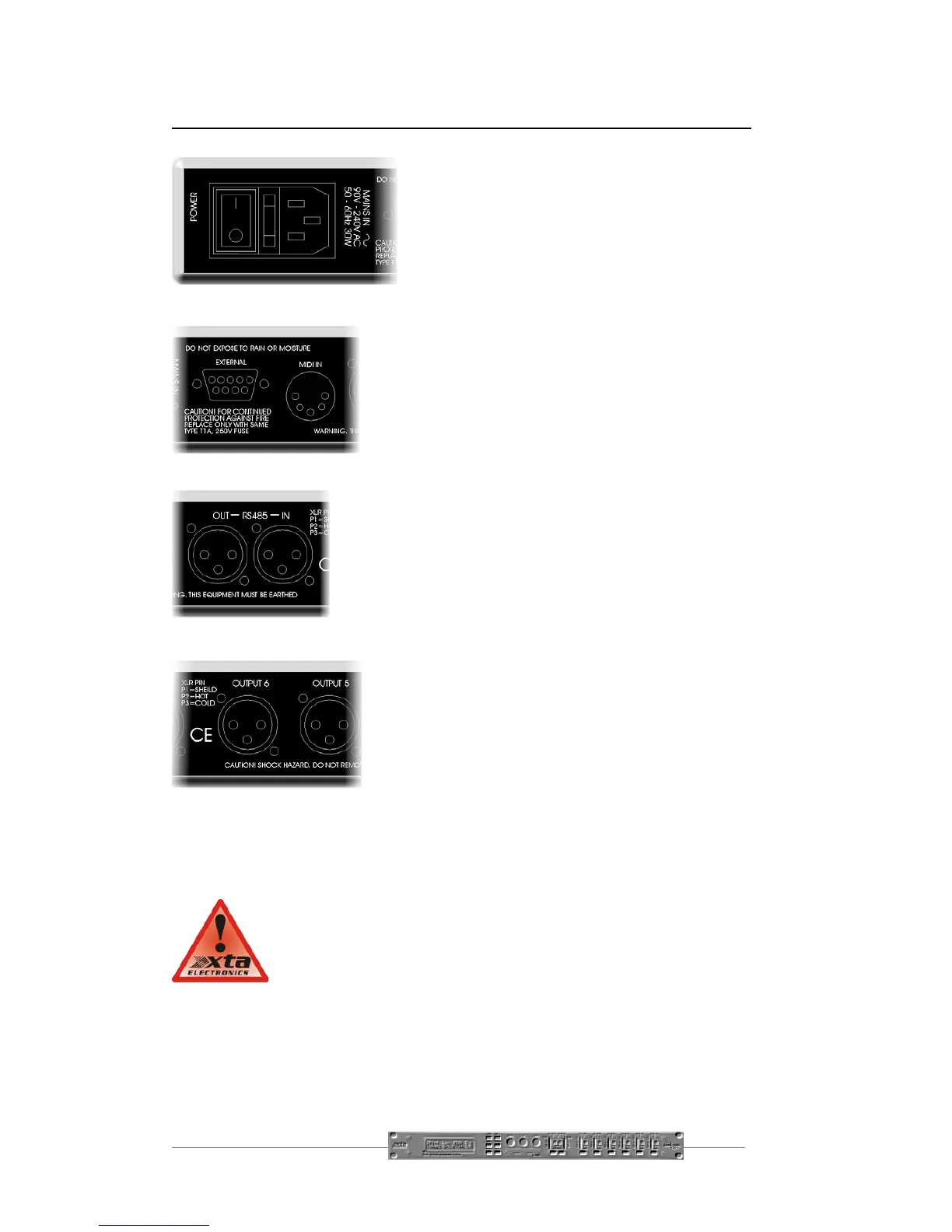
Power Switch: turns the units mains supply
off and on.
Mains Fuse: located in a finger-proof holder
adjacent to the mains inlet. A spare fuse is also
located in this holder.
Mains Inlet: connected via a standard IEC socket.
External: RS232 standard via a 9 pin D-type connector,
for connection to a PC. Data is converted to RS485
standard and relayed to slave units via the RS485 sockets.
Midi IN: 5 pin DIN socket. See page 33 for more
information.
RS485 In-Out: XLR sockets. Used for transmission of
remote control data over long distance or multiple unit
applications. See page 33 for more information.
Audio In-Out: 3 pin XLR sockets are provided for each
channel. All are fully balanced, pin 2 hot, 3 cold, 1
screen.
Always replace the fuse with the correct type and rating as
shown on the rear panel legend.
 Loading...