x
On-Screen Meters
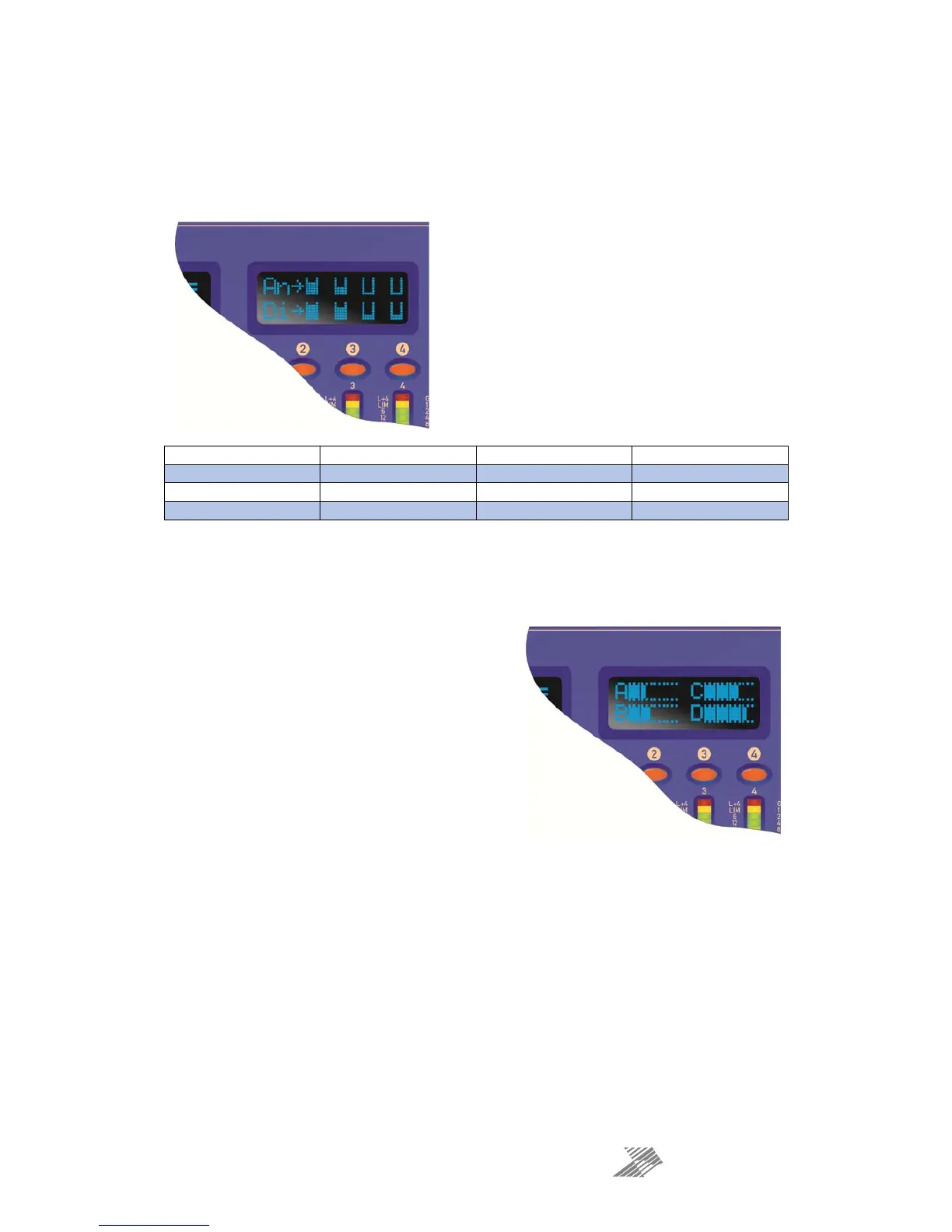
The smaller display window above the LED metering is designed to show all source level
metering and input metering. When the BANK selected is Input A-D, eight small vertical
meters are shown, representing the four analogue inputs and the four possible digital inputs,
and their respective levels. For reference, this is position #1 on the diagram on page 25.
All four analogue meters are shown even if the
channels are unavailable to monitor — for example if
analogue inputs on XLRs C&D are switched over to
AES inputs.
The digital meters show the levels of the four
possible sources available, after the source
selection, as explained on page 22.
Therefore, the digital meters may be showing one of
the following combinations:
Dante Input A Dante Input B Dante Input C Dante Input D
AES Input A (XLR C) AES Input B (XLR C) Dante Input C Dante Input D
Dante Input A Dante Input B AES Input C (XLR D) AES Input D (XLR D)
AES Input A (XLR C) AES Input B (XLR C) AES Input C (XLR D) AES Input D (XLR D)
When the BANK selected is either amplifier outputs 1-4 or auxiliary outputs 1-4, the meter
mode changes to show the post-input processing levels, prior to the mix matrix. For
reference, this is position #4 on the diagram on page 25.
The metering is the same for both amp outputs and
aux outputs as it is monitoring the inputs to the mix
matrix, and so will not be affected by output routing
or matrix mixing modes for the outputs.
 Loading...