x
Mode = Ethernet Only: The Ethernet control port on the rear panel is active.
Selecting this choice will then ask for the following further information to be confirmed:
RS485 Relay: Choose ON to relay all remote control data onto the RS485
network for connection to further devices (other DPA amplifiers or XTA processors)
RS485 Speed: Only shown if RS485 Relay = ON: set RS485 baud rate
(recommended to use 115200 unless working with older DP224 and DP226 processors
in which case use 38400)
Remote ID Number: Set a device ID (still required even on Ethernet
connections). This must be unique to the connected unit — setting the same ID on
multiple units may cause comms problems for all devices.
IP Mode: Choose either Static or Auto IP. Auto IP will generate an IP address
based on unique hardware features such as MAC address. Choose Static if you need
to select the IP address to lie within a specific range, for instance when working
within a larger infrastructure.
GtWay: The gateway address is used for external access to the Internet and
should be left at the default setting.
SubNt: The subnet mask is used to subdivide IP addresses into groups that allow
further sub-groups addressing to be defined, so further extending the address range.
Leave at default 255.255.255.0 unless specifically required.
IP: The IP address specifies the amplifier’s unique identifier on the Ethernet
network. It is used in conjunction with the amplifier’s Remote ID number to identify
individual devices on the network. Make sure this is not set to the same value as any
other devices or comms problems will occur.
All vents on front and rea r of unit m us t not be obstr ucted.
Tous les passages sur avant et arr ière de l'unité ne doivent pas être obstrués.
SERIAL NO.
CH. D
OUT
CH. C
OUT
CH. B
OUT
CH. A
OUT
Class 3 Wiring
on Outputs
BR G
OUTPUT
CO NN ECT IO N S
1+
1-
2+
2-
D+ C+ B+ A+
D- C- B- A-
D-
B+
B-
DCB A
D+
1 - AUDIO NETWORK - 2CO N TR O LGPIO PORT
1234 56
AUX 4AUX 3AUX 2 AUX 1
1: 0V
2/3: IN 1&2
4/5: OUT 1&2
6: + 5V
RS485
DESIGNED AND
MAN U FACTU R ED
IN ENGLAND BY
SERIES
A
E
S
A
&
B
A
E
S
C
&
D
All vents on front and rea r of unit m us t not be obstr ucted.
Tous les passages sur avant et arr ière de l'unité ne doivent pas être obstrués.
SERIAL NO.
CH. D
OUT
CH. C
OUT
CH. B
OUT
CH. A
OUT
Class 3 Wiring
on Outputs
BRG
OUTPUT
CO NN ECT IO N S
1+
1-
2+
2-
D+ C+ B+ A+
D- C- B- A-
D-
B+
B-
DCB A
D+
1 - AUDIO NETWORK - 2CO N TR O LGPIO PORT
1234 56
AUX 4AUX 3AUX 2 AUX 1
1: 0V
2/3: IN 1&2
4/5: OUT 1&2
6: + 5V
RS485
DESIGNED AND
MAN U FACTU R ED
IN ENGLAND BY
SERIES
A
E
S
A
&
B
A
E
S
C
&
D
All vents on front and rea r of unit m us t not be obstr ucted.
Tous les passages sur avant et arr ière de l'unité ne doivent pas être obstrués.
SERIAL NO.
CH. D
OUT
CH. C
OUT
CH. B
OUT
CH. A
OUT
Class 3 Wiring
on Outputs
BR G
OUTPUT
CO NN ECT IO N S
1+
1-
2+
2-
D+ C+ B+ A+
D- C- B- A-
D-
B+
B-
DCB A
D+
1 - AUDIO NETWORK - 2CO N TR O LGPIO PORT
1234 56
AUX 4AUX 3AUX 2 AUX 1
1: 0V
2/3: IN 1&2
4/5: OUT 1&2
6: + 5V
RS485
DESIGNED AND
MAN U FACTU R ED
IN ENGLAND BY
SERIES
A
E
S
A
&
B
A
E
S
C
&
D
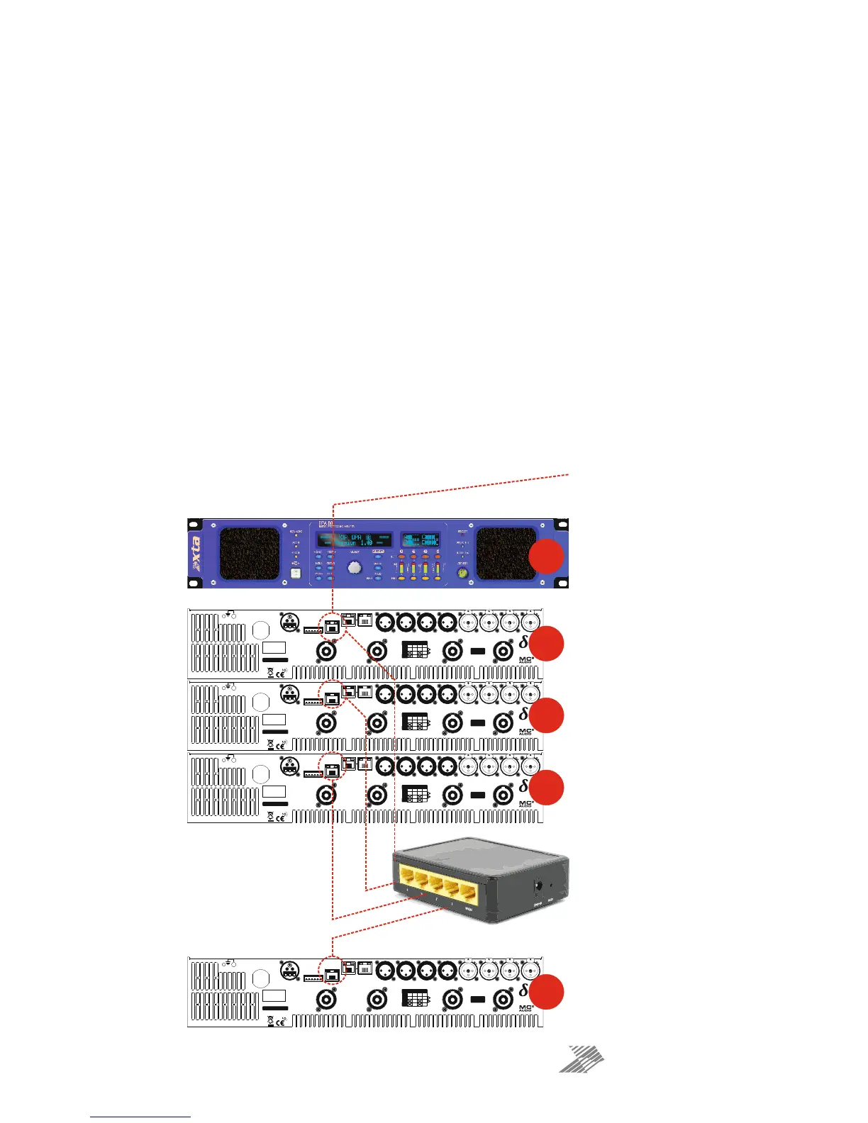
Ethernet to PC
Connect to all units with standar
CAT5 Ethernet cable to router.
This unit’s interface set as:
Mode: Ethernet Only
RS485 Relay: Off
Remote ID Number: 1
IP Mode: Auto IP
Rear of First Unit
“Control” Port to Router with
CAT5 Ethernet Cable
Rear of Next Unit
“Control” Port to Router with
CAT5 Ethernet Cable
This unit’s interface set as for #1
EXCEPT
Remote ID Number: 2
All vents on front and rea r of unit m us t not be obstr ucted.
Tous les passages sur avant et arr ière de l'unité ne doivent pas être obstrués.
SERIAL NO.
CH. D
OUT
CH. C
OUT
CH. B
OUT
CH. A
OUT
Class 3 Wiring
on Outputs
BRG
OUTPUT
CO NN ECT IO N S
1+
1-
2+
2-
D+ C+ B+ A+
D- C- B- A-
D-
B+
B-
DCB A
D+
1 - AUDIO NETWORK - 2CO N TR O LGPIO PORT
1234 56
AUX 4AUX 3AUX 2 AUX 1
1: 0V
2/3: IN 1&2
4/5: OUT 1&2
6: + 5V
RS485
DESIGNED AND
MAN U FACTU R ED
IN ENGLAND BY
SERIES
A
E
S
A
&
B
A
E
S
C
&
D
Rear of Next Unit
“Control” Port to Router with
CAT5 Ethernet Cable
This unit’s interface set as for #1
EXCEPT
Remote ID Number: 3
Rear of Last Unit
“Control” Port to Router with
CAT5 Ethernet Cable
This unit’s interface set as for #1
EXCEPT
Remote ID Number: N
#1
#1
#2
#3
#N
 Loading...