ADPROPROE by Xtralis Installation Guide
27386_05 35
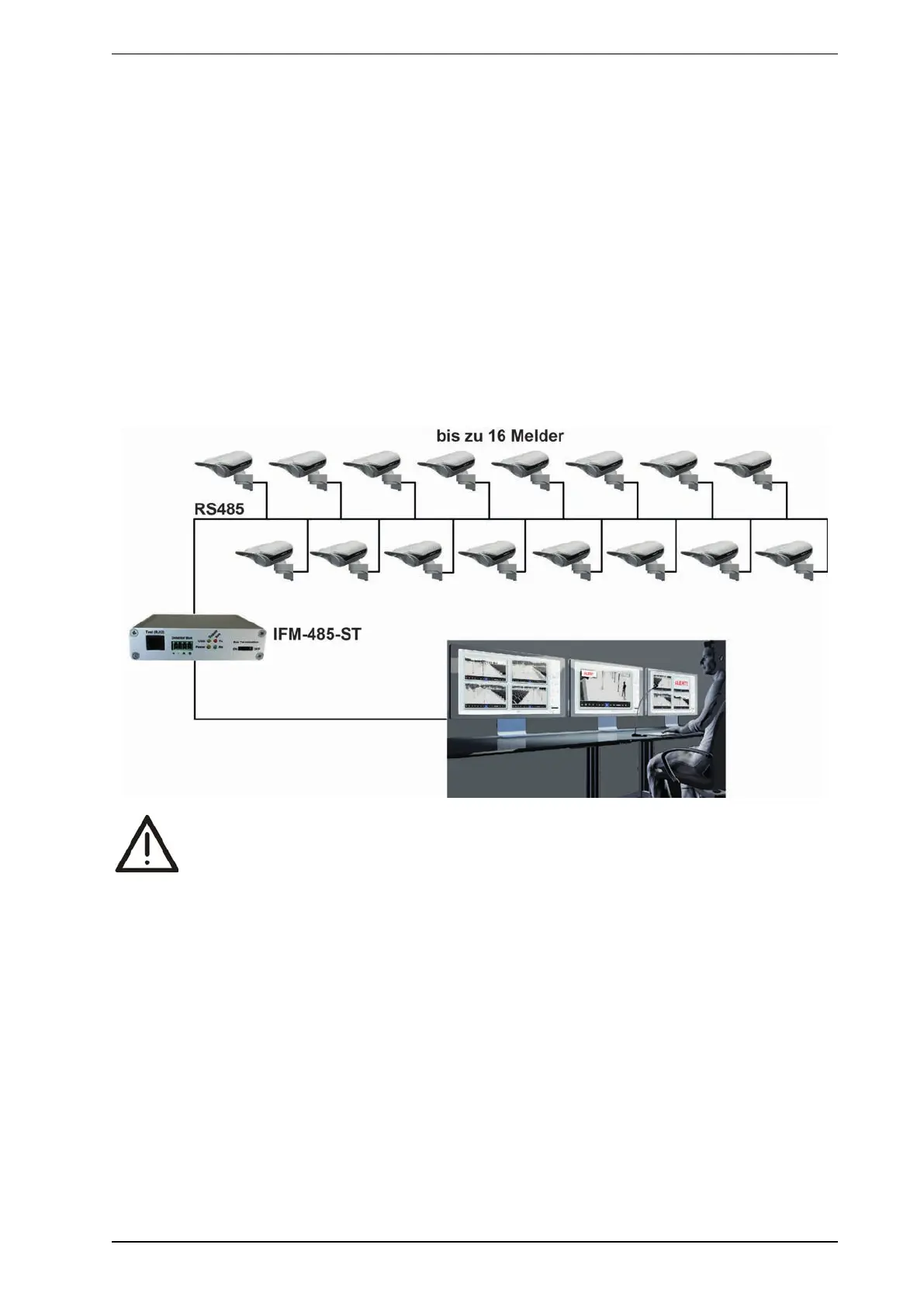
5.2.2 Multiple detectors at interface module IFM-485-ST
Perform the following steps to connect more than one detector to a PC via the RS485 data bus:
1. First, connect each detector individually to a computer on which the PRO software is installed and assign
it an individual address (1-255) in the software settings. Each address may be allocated only once.
2. The detectors can then be interconnected through parallel or star cabling.
3. Add a terminating resistor of 120 Ω between the RS485 and RS485 B connections on the circuit board of
the last detector in the bus. The (switched) resistor is already built into the interface module IFM-485-ST.
This completes the data connection to both ends of the bus.
Ensure that the total cable length (including tap holes) does not exceed 1000 m.
Notes:
l If more than one detector is connected to interface module IFM-485-ST, every detector must have a
unique address.
l To avoid malfunctioning or permanent damage to devices that may occur due to potential differences,
ensure that the GND connections in all detectors and the interface module IFM-485-ST are
interconnected.
WARNING:
If the IFM-485-ST as well as all PIR detectors are supplied AC voltage, it is absolutely
necessary to ensure that all detectors and the IFM are connected identically and L1 (+) and N (-)
are nowhere interchanged.
Otherwise, there could be substantial damage to detectors other than the detector with reversed
polarity due to overheating as soon as the RS-485 bus and its ground (earth) are connected.
This would be due to the formation of a potential difference of 24VAC between the grounds
(earth) of two PIR detectors. See following diagram:
Note: To eliminate confusion and make your work easier, we recommend the use of colored or coded
cables – especially if AC voltage is used.