4.3.1 Prepare for alignment
The standard coupling selection for e-XC pumps are TB Wood’s
®
Dura-Flex
®
non-spacer
elastomeric couplings and Falk
®
Steelflex
®
Type T10 close-coupled grid couplings. For
other coupling types or brands, refer to the coupling manufacturer’s installation
instructions and alignment data. Always consult the coupling manufacturer’s installation
manual for detailed instructions and the most up-to-date service information.
1. Check the pump and motor shafts and remove any paint, burrs, and rust.
2. Slide the hubs and bushings on the shafts with keys.
3. Hold one half element on the hubs in order to determine the appropriate hub spacing.
4. If you use spacer elements with high speed rings, hold both half elements on the hubs
in order to make sure the hubs do not interfere with the rings.
5. You can install the hubs with the hub extension facing in or out. Make sure the shaft
extends into the hubs at least 0.8 times the diameter of the shaft.
6. Lightly fasten the hubs to the shafts in order to prevent them from moving during
alignment.
7. Align the hubs to the values shown in ‘Maximum allowable coupling misalignment’.
Alignment may be performed with lasers, dial indicators, or with a straight edge and
calipers.
4.3.2 Align the pump using a straight edge and calipers
1. Check the angular misalignment:
Tool Procedure
Calipers 1. Gauge the distance between the two hubs at various points around the circumference. Do not
rotate the shafts.
2. Reposition the equipment until the difference between the minimum and maximum
distance values is within the permissible range.
Feeler
gauges
1. Insert feeler gauges between the coupling faces at various points around the circumference.
Do not rotate the shafts.
2. Reposition the equipment until the difference between the minimum and maximum
distance values is within the permissible range.
2. Check the parallel alignment:
a) Place a straight edge across the two hubs.
b) Measure the maximum offset at various points around the periphery of the hubs.
Do not rotate the shafts.
c) Reposition the equipment until the offset is within the permissible range.
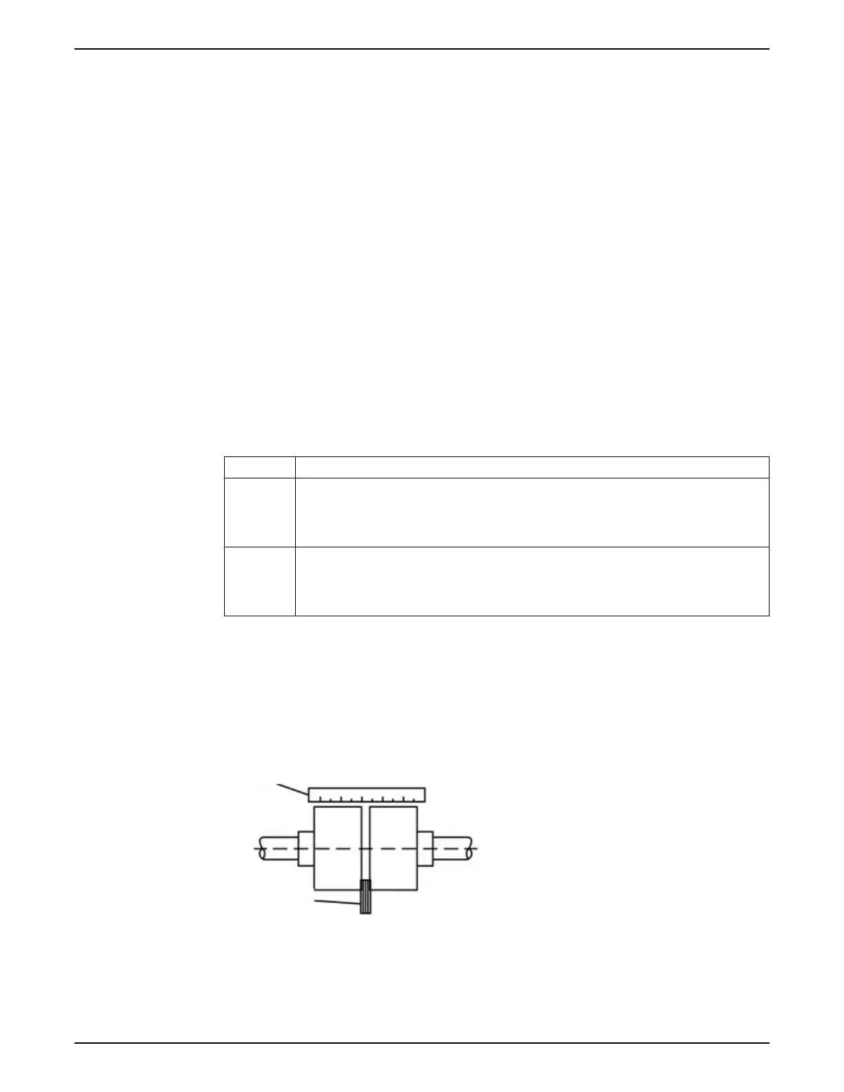
The following figure demonstrates an acceptable alignment where both
the parallel and angular alignments are correct.
1. Straight edge
2. Feeler gauge
Figure 4: Check the alignment using a straight edge - correct
4 Installation
22 e-XC INSTRUCTION MANUAL