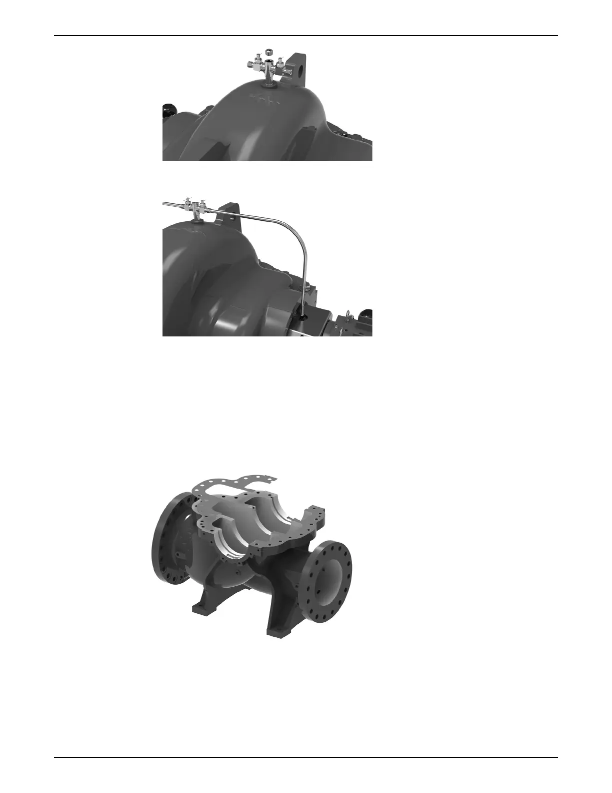
11.Route the flush line piping between the valve and the bite-type fitting located on top
of the seal gland. Ensure connections are secure and water-tight.
12.Unless installing pressure sensors, ensure all plugs located on either side of the lower
casing are inserted.
6.6.3 Pump assembly for pumps with drop-in stuffing box and sleeveless shaft (wet shaft)
design
All bearings, O-rings, seals and gaskets should be replaced with new parts during
reassembly. Any other parts that are reused should be thoroughly cleaned before
reassembly. The main casing joint gasket should be trimmed according to the parting
flange profile of the lower casing. Ensure the gasket is flush with the inside edges of the
casing.
Note: Assemble the outboard side elements of the pump first for any given assembly
category.
Impeller assembly
1. Place the impeller key(s) in the shaft key slot.
2. Place the impeller on V-blocks or stands such that the impeller bore direction is
parallel to the ground. The shaft will be horizontally inserted into the impeller bore.
6 Maintenance
84 e-XC INSTRUCTION MANUAL