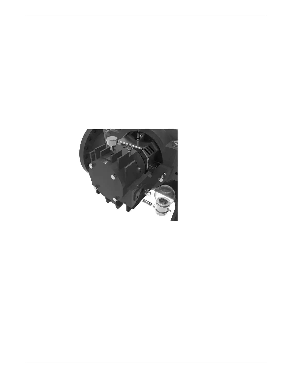
6.6.4 Oil lubrication for bearings assembly
Before assembling oiler components ensure all required oiler kit accessories are on hand.
Oiler kits should include (2) glass bulb oilers, (2) NPT pipe nipples, (2) NPT sight glasses,
(2) NPT breather vents, and (4) pipe plugs.
1. Choose a side of the pump that is the most accessible for the area it is installed. The
oilers and sight glasses should be installed on the chosen side.
2. Thread the NPT pipe nipple into the smaller diameter hole on the side of the bearing
housing.
3. Thread the sight glass into the larger diameter hole on the side of the bearing
housing.
4. Thread the breather vent into the outermost hole located on top of the bearing
housing.
5. Fasten the metal oiler housing onto the pipe nipple.
6. Install the pipe plugs into the holes not being used opposite of the oiler assembly.
7. Fill the oiler to the desired amount and install the glass bulb atop the metal housing.
See Bearing and coupling lubrication on page 38 for more detailed instructions
6.6.5 Pump assembly for pumps with integrated stuffing box design
The assembly process for pumps with an integrated stuffing box may be considered
identical to the drop-in stuffing box design with a few minor differences. Please note
differences outlined below and then refer to Pump assembly for pumps with drop-in
stuffing box and sleeve over shaft (dry shaft) design on page 65 for seal on sleeve (dry
shaft) configurations and Pump assembly for pumps with drop-in stuffing box and
sleeveless shaft (wet shaft) design on page 84 for sleeveless (wet shaft) configurations.
Follow all safety procedures outlined in Pump assembly on page 65.
MR2 & MR4 Mechanical Seals
1. When following the drop-in stuffing box assembly instructions for seal installation,
lower the impeller and shaft assembly, with drive rings and shaft sleeves (if applicable),
into the lower casing before attempting to install the stationary mechanical seal face
and seal gland.
2. The upper casing must be fastened to the lower casing before installing both the
rotating and stationary elements of the mechanical seal.
MR1 & MR3 Mechanical Seals
1. When following the drop-in stuffing box assembly instructions for seal installation,
lower the impeller and shaft assembly, with shaft sleeves (if applicable), into the lower
casing before attempting to install the stationary mechanical seal face and seal gland.
6 Maintenance
e-XC INSTRUCTION MANUAL 91