pg | 39
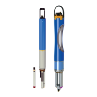
4 C onnect flying lead cable to sonde.
Press in the male 6-pin connector, then screw down the
retaining collar. Attach the cable’s strain relief to the sonde’s
bail with a carabiner. e cable’s strain relief should be
positioned to remove any weight-bearing from the actual
connector and retaining collar.
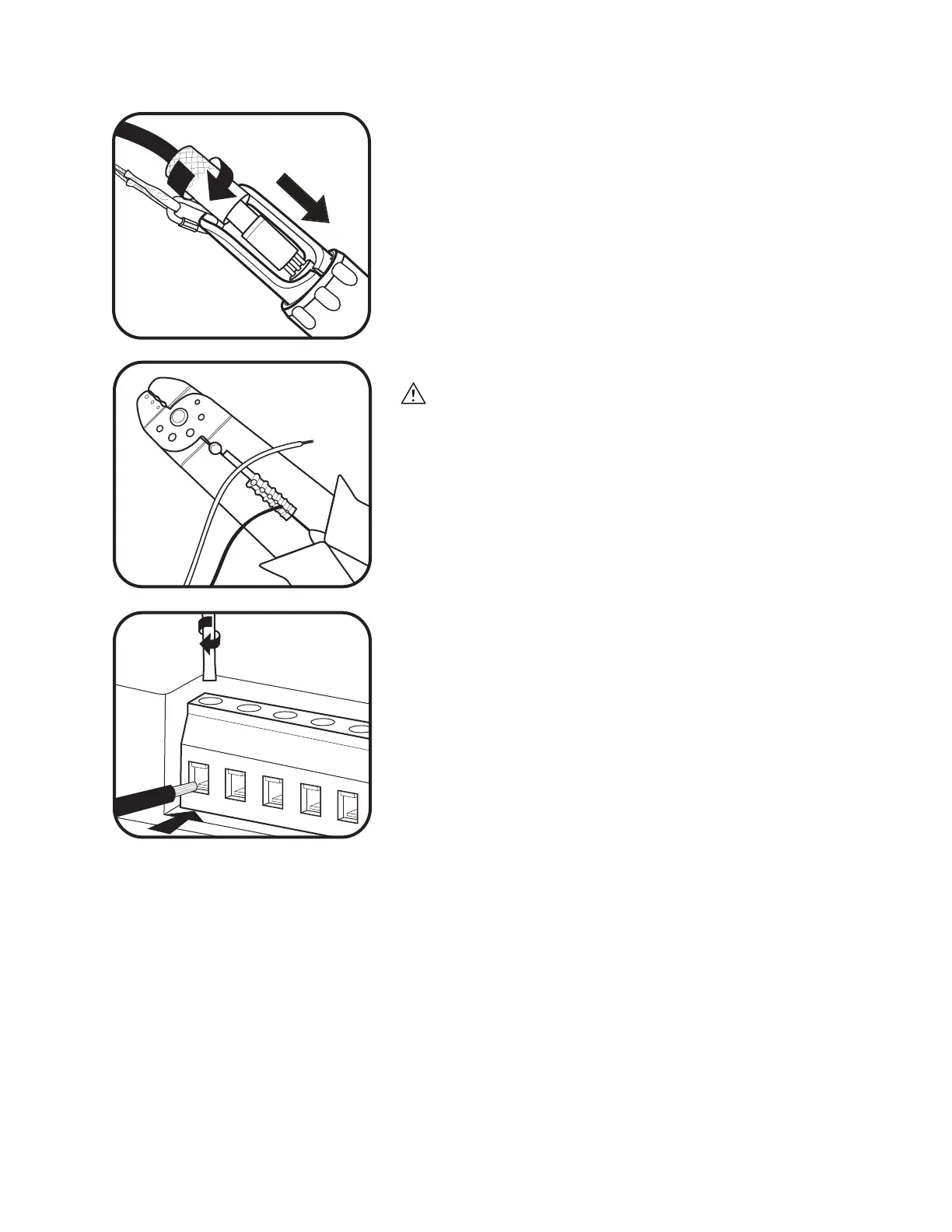
5 Prepare wires.
Always follow proper safety precautions when performing
electrical work.
Properly strip the ends of the wire. Remove 0.25 inches
of insulation from each wire then twist the bared strands
together. All wires should be 18-24 AWG and are not
included with the SOA.
6 Insert wires into SOA.
Loosen the clamping screw with the supplied screwdriver,
insert the indicated wire into the terminal strip, and tighten
the clamping screw back down onto the exposed wire end.
Ensure that all strands are inserted to avoid short circuits.
Take care not to strip the slots in the heads of the screws.
• Connect DCP signal ground to SOA SDI ground terminal
(recommend black wire)
• Connect DCP SDI-12 data terminal for SOA SDI-12
terminal (recommend violet wire)
• Connect DCP output ground terminal to SOA power
ground terminal (recommend black wire)
• Connect DCP 12 VDC output to SOA 9-16 VDC input
terminal (recommend red wire).
 Loading...