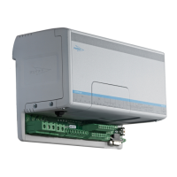
Terminals
1 2 3
4
5
6
7 8
9
1011
Control Terminal Unit 1
1 2 3 4 5 6
Power terminal Unit 1 and 2
Control Terminal Unit 2
3
1
2
4
5
6
7
8
9
10
11
12
15
16 19
20
21
22
23
18
25
26
27
28
13
24
WS003610
12
13 1 2 3
4
5
6
7 8
9
1011
12
13
M
M
14
17
1. Incoming power
2. RFI-toroid core, for sizes 2 and 3
3. Brown lead
4. Black lead
5. Gray cable
6. Ground (earth)
7. Pump 1
8. T1 (pump 1)
9. T2 (pump 1)
10. T3
1
(pump 1)
11. T4
1
(pump 1)
12. Black lead
13. Control screen
14. Level switch
15. • Gray lead (EU)
• Red lead (US)
16. Screen of the shared communication cable
17. Signal leads of the shared communication cable
18. Pump 2
19. T1 (pump 2)
20. T2 (pump 2)
21. T3
1
(pump 1)
22. T4
1
(pump 1)
23. Screen of the shared communication cable
24. Screen of the level sensor cable
25. Level sensor
26. Blue lead
27. Red lead
28. White
Figure 1: Electrical connection drawing
Table 1: Power
Terminal Type Function
1 L1/L Incoming power to the drive
2 L2/N Incoming power to the drive
3 L3 Incoming power to the drive
4 U Outgoing power for the pump
5 V Outgoing power for the pump
1
If available
Installation
SRC 311 - SmartRun
™
User guide 13

 Loading...