CL Editor Owner’s Manual
33
7 RATIO
Specifies the ratio (the amount of compression.)
8 WIDTH
Specifies the width between the threshold level of the compressor (THRESHOLD) and the threshold level of the
expander.
9 ATTACK
Specifies the time (the attack time) until it starts to compress and expand the input signal once the compander has been
triggered.
0 GAIN
Adjusts the gain of the signal after it has passed through the compander.
A RELEASE
Specifies the time (the release time) from when the key-in signal falls below the threshold level until compression and
expansion are removed.
B KEY IN SOURCE
Click this to select the key-in signal that you want to use.
The choices are the same as for GATE.
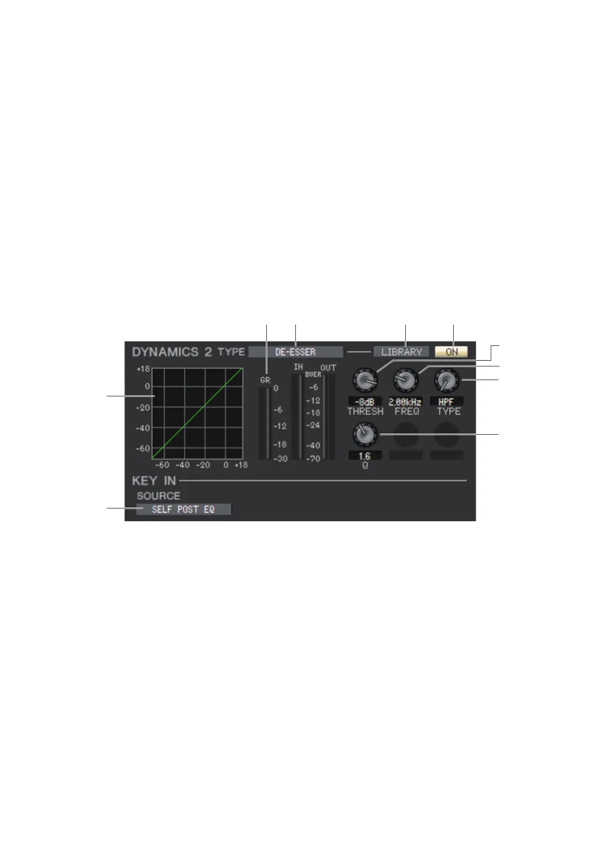
If DE-ESSER is selected
1 TYPE
This indicates that De-Esser is the currently selected type.
2 LIBRARY
This button accesses the dynamics library. Clicking this button will open the DYNAMICS page of the Library window.
3 ON
This button switches the de-esser on/off.
4 Response curve
Indicates the response for the de-esser of the currently selected channel.
5 GR meter (Gain Reduction meter)
This meter indicates the amount of gain reduction produced by the de-esser.
6 THRESH (Threshold level)
Specifies the threshold level at which the de-esser will operate. The input signal will start being compressed when the
key-in signal exceeds this level; compression will be removed when the signal falls below this level.
7 FREQ (Minimum frequency/Center frequency)
Specifies the minimum frequency (for HPF) or the center frequency (for BPF) at which the key-in signal will activate
the de-esser.