Channel Strip Displays 39
DM2000—Owner’s Manual
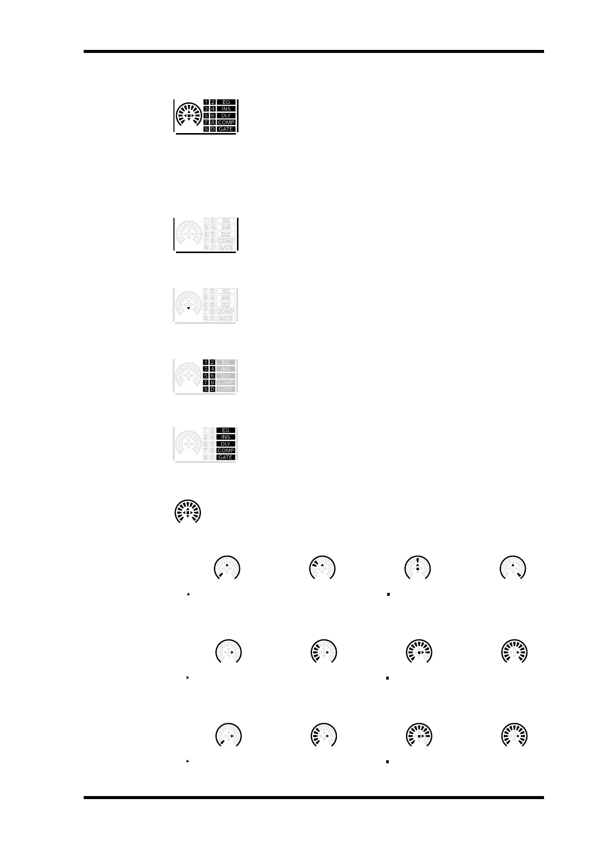
Channel Strip Displays
The fluorescent channel strip displays graphically display the value of the
Input or Output Channel parameter currently assigned to the Encoders,
routing settings, and the on/off status of the EQ, Insert, Delay, Comp,
and Gate functions. They also display the Long and Short channel names
and indicate the currently selected channel. You can adjust their bright-
ness by using the Channel Strip Display Brightness preference on
page 236.
Selected Channel
The border of the currently selected channel’s channel strip display lights
up like this.
Fader Touch Sense
When fader knobs are touched, the corresponding Touch Sense indica-
tors light up like this.
Routing Indicators
These indicators show to which Output Channels an Input Channel is
being routed: 1 through 8 being the Bus Outs, “S” being the Stereo Out,
and “D,” the Direct Out.
EQ, Insert, Delay, Comp & Gate Indicators
These indicators show whether a channel’s EQ, Insert, Delay, Comp, and
Gate functions are on or off.
Encoder Displays
Operation of the Encoder displays depends on the parameter assigned to the
Encoders, as follows.
Pan Mode
Aux/Mtrx Mode
Attenuator Parameter & Surr LFE Level
CH01
( indicates at center)
Hard left
( indicates center position)
Other position Center Hard right
( indicates nominal position) ( indicates at nominal)
Minimum (–∞) Other position Nominal Maximum
( indicates nominal position) ( indicates at nominal)
Minimum (–96 dB) Other position Nominal Maximum