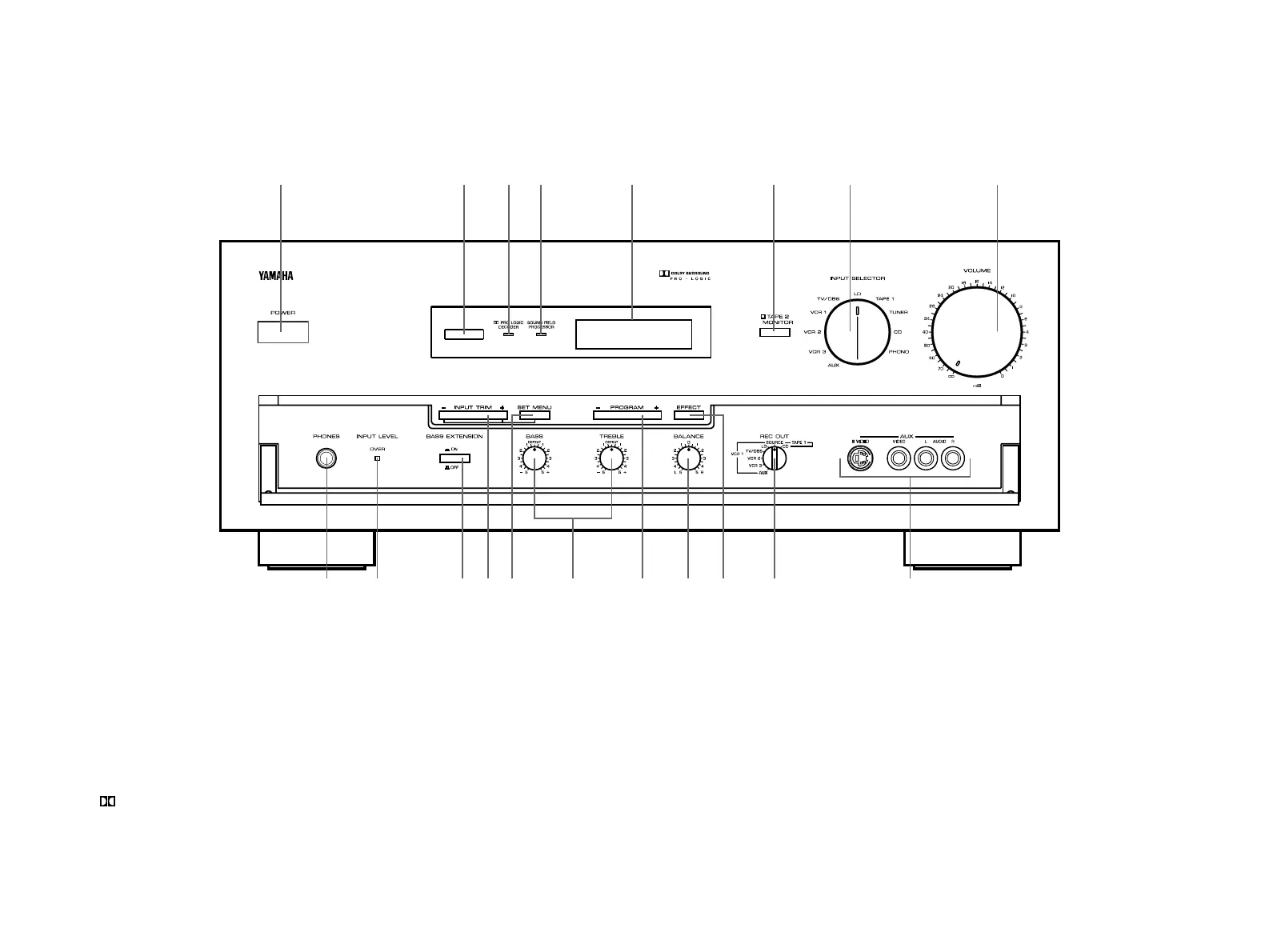
1-3. CONTROLS & ADJUSTMENTS
FRONT PANEL
19
1Power Switch
*STANDBY Mode (Europe model only)
While the power is on, pressing the POWER key on the remote
control unit switches the unit to the STANDBY mode. (In this
mode, the indicator is half illuminated.)
2Remote control sensor
Signals from the remote control unit are received here.
3 Pro Logic Decoder Indicator
Illuminates while the built-in Dolby Pro Logic Surround Decoder is
being activated.
4Sound Field Processor Indicator
Illuminates while the built-in Sound Field Processor is being
activated.
5Display Panel
Shows program names, parameters and information about other
various settings and adjustments.
6Tape 2 Monitor Switch
Used when you have connected a second tape deck to this unit’s
AUDIO SIGNAL TAPE 2 terminals to select that tape as the
source.
1
9 0 A DB E F HGC
34 5 6 7 82
I
(General Model)

 Loading...