21
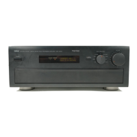
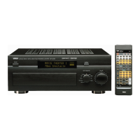
DSP-A595a
IC800 : LC876564A-5M19
8 bit Main
µ-COM
Pin Pin
Port I/O Function
No. Name
1 P16 FLA-CLK I/O Flash clock
2 P17 FLA-I/O I/O Flash input/output
3 P30 FLA-SEL I/O Flash select
4 P31 T-MUTE O Tuner mute (L: ON)
5 P32 DSP-MTS O Transmit data for Sub µ-COM
6 P33 DSP-STM I Receive data from Sub µ-COM
7 P34 DSR-SCK O Clock for Sub µ-COM
8 P35 DSP-RTN I Clock from Sub µ-COM
9 P36 DSP-TRQ I Transmit request from Sub µ-COM
10 P37
DSP-RESET
O Reset for Sub µ-COM
11 /RES /RES System reset
12 XT1 T-/ST I Stereo from Tuner
13 XT2 Unconnected
14 Vss1 Vss1 Ground
15 CF1
Ceramic Oscillator Connected (10MHz)
16 CF2
Ceramic Oscillator Connected (10MHz)
17 VDD1 VDD1 Power supply
18 P80/AN0 KEY1 I Key 1 AD input
19 P81/AN1 KEY2 I Key 2 AD input
20 P82/AN2 KEY3 I Key 3 AD input
21 P82/AN3 KEY4 I Key 4 AD input
22 P84/AN4 T-METER I Tuner meter AD input
23 P85/AN5 PRO1 I Protection 1 detect (PRD)
∗1
24 P86/AN6 PRO2 I Protection 2 detect (PRI)
∗1
25 P85/AN5 PRO3 I Protection 3 detect
(PRV1) ∗1
Pin Pin
Port I/O Function
No. Name
26
P70/INT0
PDT I Power down detect
27
P71/INT1
FMT O Full mute (L : ON)
28
P72/INT2
I/O Unconnected
29
P73/INT3
REMOTE I Remote Control signal
30 S0/T0 G1 O FL Grid 1
31 S1/T1 G2 O FL Grid 2
32 S2/T2 G3 O FL Grid 3
33 S3/T3 G4 O FL Grid 4
34 S4/T4 G5 O FL Grid 5
35 S5/T5 G6 O FL Grid 6
36 S6/T6 G7 O FL Grid 7
37 S7/T7 G8 O FL Grid 8
38 S8/T8 G9 O FL Grid 9
39 S9/T9 G10 O FL Grid 10
40 S10/T10 G11 O FL Grid 11
41 S11/T11 G12 O FL Grid 12
42 S12/T12 G13 O FL Grid 13
43 S13/T13 G14 O FL Grid 14
44 S14/T14 G15 O FL Grid 15
45 S15/T15 G16 O FL Grid 16
46 VDD3 VDD3 Power supply
47 S16/PC0 P1 O FL Segment 1
48 S17/PC1 P2 O FL Segment 2
49 S18/PC2 P3 O FL Segment 3
50 S19/PC3 P4 O FL Segment 4
∗1 Protection 1, 2 and 3 detect
• After a few seconds the Power ON, and protection detect start.
Detection
Protection 1 Abnormal DC of the amplifier.
Protection 2 Abnormal overcurrent of the amplifier.
Protection 3 Abnormal Voltage of the amplifier.


 To Next Page