5-9
E
POWR
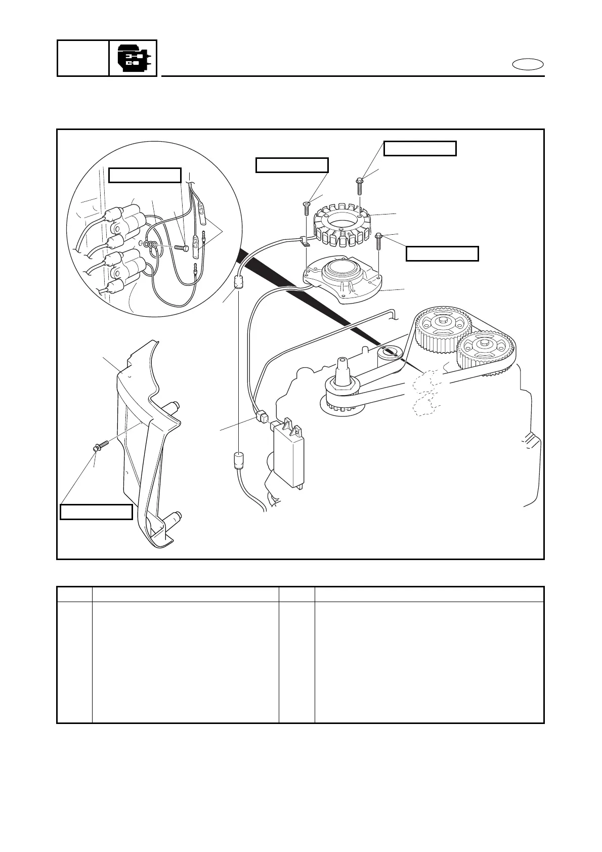
STATOR COIL ASSY.
STATOR COIL ASSY.
EXPLODED DIAGRAM
A
A
4
9
8
7
5
6
11
2
1
10
3
12
4 × 10 mm
6 × 20 mm
6 × 28 mm
6 × 30 mm
6 × 30 mm
REMOVAL AND INSTALLATION CHART
Step Procedure/Part name Q’ty Service points
STATOR COIL ASSY. REMOVAL
Follow the left “Step” for removal.
Flywheel magneto Refer to “FLYWHEEL MAGNETO”.
1 Screw 3
2 CDI unit cover 1
3 Lighting coil coupler 1
4 Screw 1
5 Bolt 3
6 Stator coil assy. 1