5-27
ELEC
Electrical system
3. Turn the engine start switch to OFF, and
then disconnect the SPS coupler a.
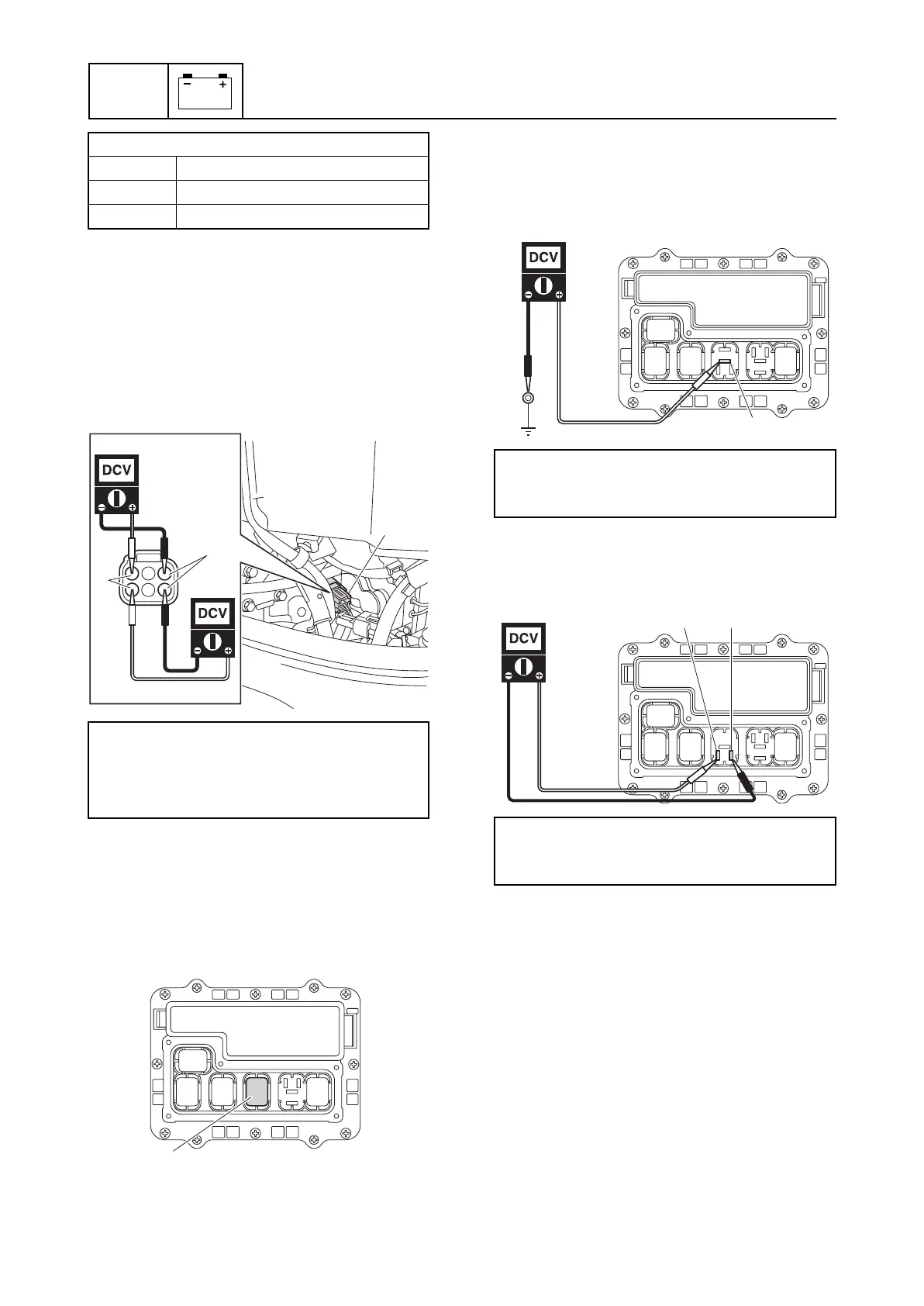
4. Turn the engine start switch to ON, and
then measure the input voltage at the
SPS coupler. Check the wiring harness if
out of specification. See “Checking the
SPS and shift actuator circuit” (5-28).
5. Turn the engine start switch to OFF, and
then connect the SPS coupler a.
Checking the shift actuator relay
1. Remove the relay cover and shift actua-
tor relay a.
2. Check the shift actuator relay. See
“Checking the main relay” (5-22).
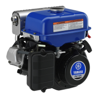
3. Measure the input voltage between the
terminal a and ground.
4. Turn the engine start switch to ON, and
then measure the input voltage between
terminals b and c.
5. Turn the engine start switch to OFF.
6. Install the shift actuator relay a and relay
cover.
Checking the shift actuator
1. Remove the intake manifold (PORT).
2. Operate the Digital Electronic Control to
check the shift actuator rod stroke a at
the positions F, N, and R.
SPS output voltage:
F 0.2–1.5 V
N 2.412–2.588 V
R 3.5–4.8 V
SPS input voltage:
A SPS 1: Orange (O)–Black (B)
B SPS 2: Orange (O)–Black (B)
4.75–5.25 V
A
B
O
B
a
a
Shift actuator relay input voltage:
Terminal a–Ground
12.0 V (battery voltage)
Shift actuator relay input voltage:
Terminal b–Terminal c
12.0 V (battery voltage)
a
c
b