5-38
Fuel control unit and component
0
1
2
3
4
5
6
7
8
9
10
A
8. Remove the intake manifold (STBD).
9. Remove the fuse holder c, and then
disconnect the fuse holder couplers c
and d.
10. Disconnect the engine ECM coupler e.
11. Check the wiring harness for continuity.
12. Connect the fuse holder coupler c and
d, and then install the fuse holder c.
13. Install the intake manifold (STBD). See
“Installing the intake manifold” (6-16).
14. Connect the engine ECM coupler e.
15. Connect the low-pressure fuel pump
coupler a and high-pressure fuel pump
coupler b.
Checking the high-pressure fuel
pump relay
1. Remove the relay cover and high-pres-
sure fuel pump relay a.
2. Check the high-pressure fuel pump relay.
See “Checking the main relay” (5-22).
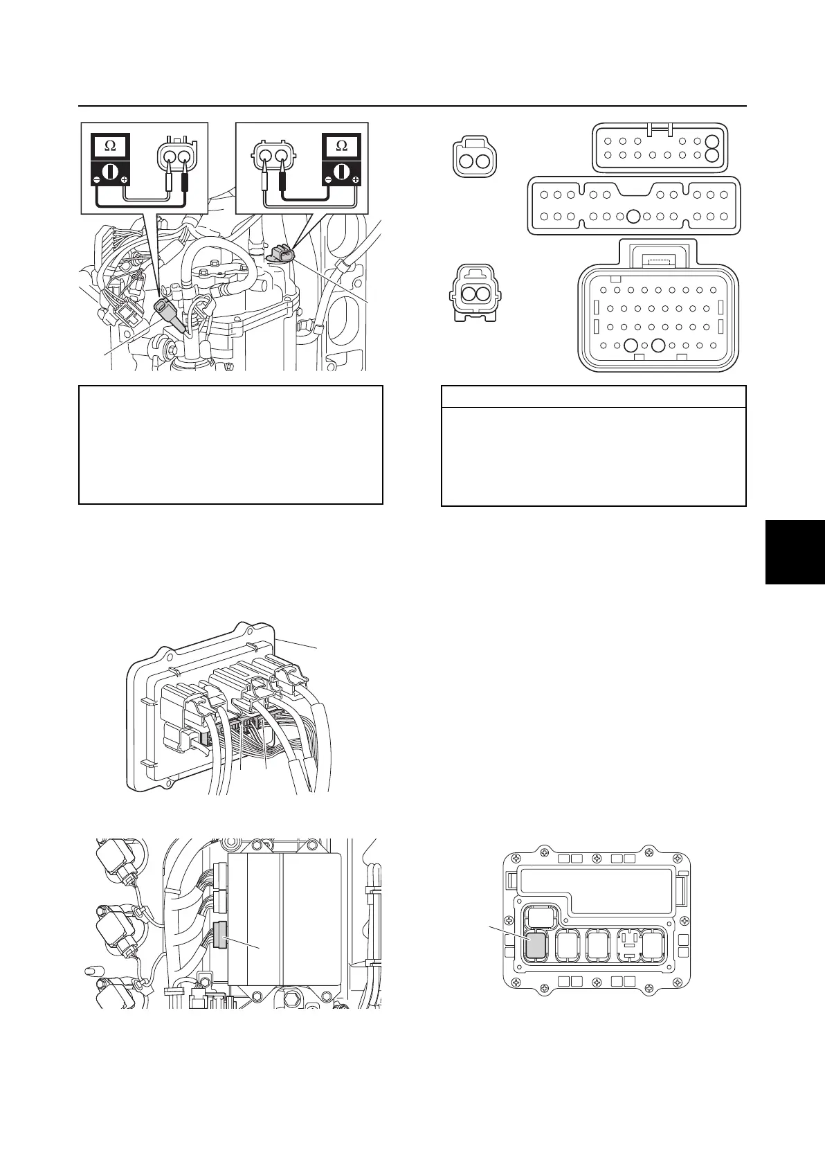
Low-pressure fuel pump a resistance
(reference data):
0.5–4.0 Ω at 20 °C (68 °F)
High-pressure fuel pump b resistance
(reference data):
0.2–3.0 Ω at 20 °C (68 °F)
a
b
d
c
c
e
Wiring harness continuity:
a Terminal 1–c Terminal 7
a Terminal 2–e Terminal 56
b Terminal 1–c Terminal 1
b Terminal 2–Ground
e Terminal 58–d Terminal 17
12
5
a
e
b
c
d
17
7
1
58 56
2
2 1
1
a



 To Next Page