7-83
Power unit
POWR
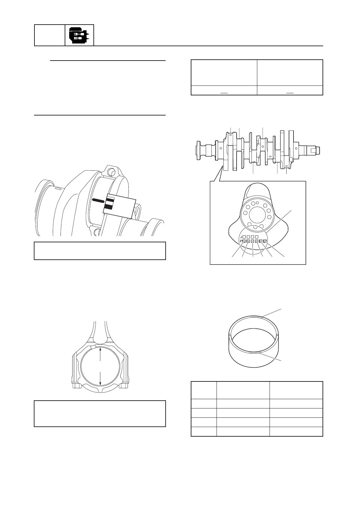
TIP:
In the second tightening stage for the con-
necting rod bolts b, mark the connecting rod
bolts and the connecting rod cap with identifi-
cation marks e, and then tighten the bolts
90° from the marks on the connecting rod
cap.
6. Remove the connecting rod cap, and
then measure the width of the
compressed Plastigauge (PG-1) on the
crankpin.
Selecting the crankpin bearing
When replacing the crankpin bearing, select
the bearing as follows:
1. Measure the connecting rod big end
inside diameter a.
Example:
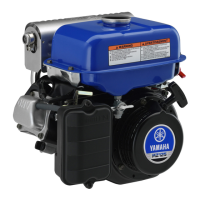
2. Check the crankpin mark b on the
crankshaft.
3. Select the suitable colors c for the
crankpin bearing from the “Crankpin
bearing selection table.”
Crankpin oil clearance (reference data):
0.025–0.050 mm (0.0010–0.0020 in)
Connecting rod big end inside diameter a:
55.990–56.010 mm
(2.2043–2.2051 in)
a
Connecting rod big
end inside diameter
a
Number in table
56.005
mm 05
Upper bearing
color
Lower bearing
color
d Ye ll o w Ye l l o w
e Yellow Green
f Green Green
g Blue Green
P1
P1
P2
P2
P3
P3
P4
P4
P5
P5
P6
P6
b
c
c