5-69
ELEC
Electrical system
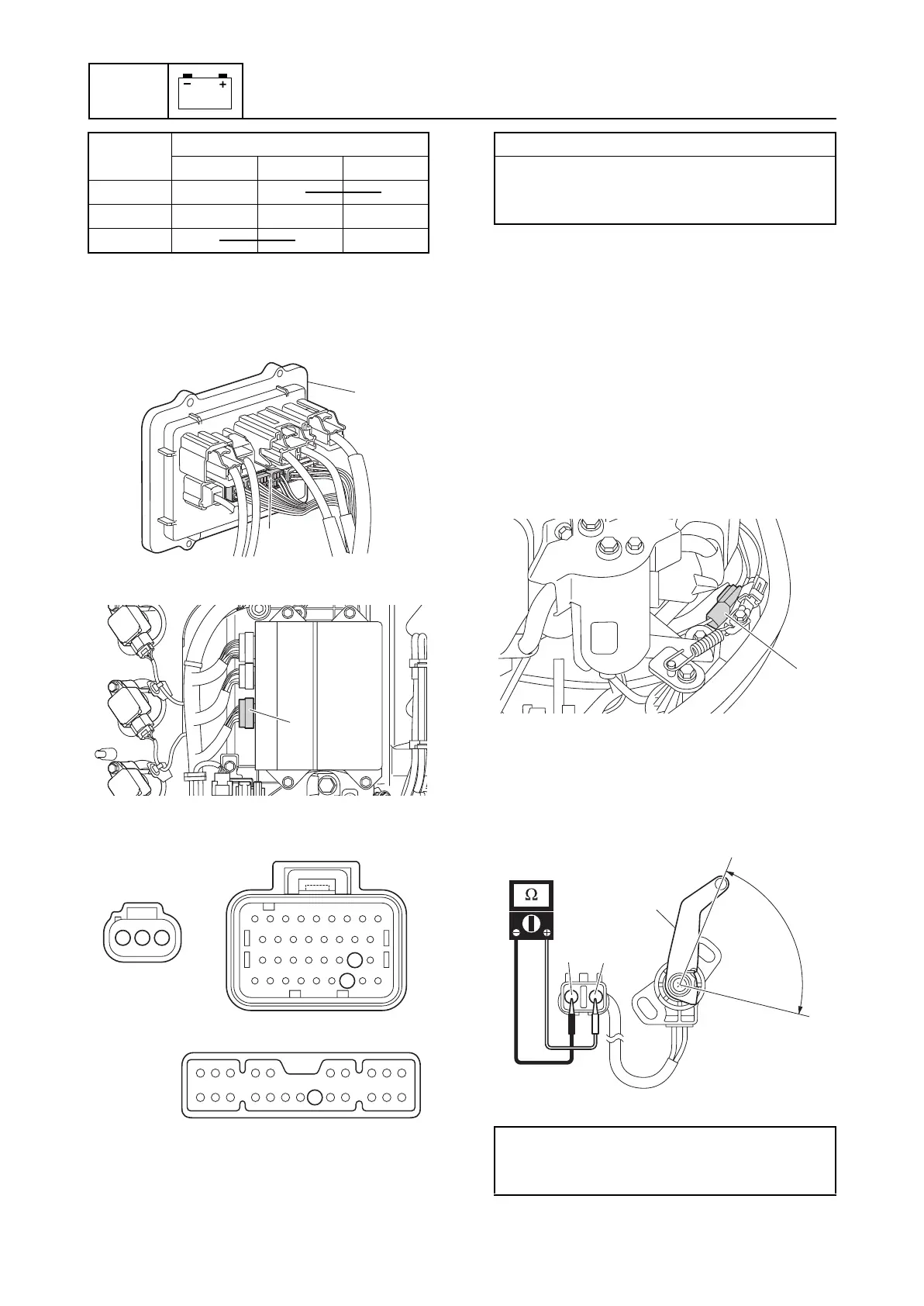
4. Remove the intake manifold (STBD).
5. Remove the fuse holder a, and then
disconnect the fuse holder coupler e.
6. Disconnect the engine ECM coupler f.
7. Check the wiring harness for continuity.
8. Connect the fuse holder coupler e, and
then install the fuse holder a.
9. Install the intake manifold (STBD). See
“Installing the intake manifold” (6-16).
10. Connect the engine ECM coupler f.
11. Connect the PTT switch coupler a.
Checking the trim sensor
1. Disconnect the trim sensor coupler a,
and then remove the trim sensor.
2. Turn the trim sensor lever b from the
position c to the position d, and then
measure the resistance as it gradually
changes.
Switch
position
Terminal
bcd
UP CC
Free
DN CC
e
a
f
16
54
45
a
e
f
3 2 1
Wiring harness continuity:
Terminal 1–Terminal 54
Terminal 2–Terminal 16
Terminal 3–Terminal 45
Trim sensor resistance:
247.6–387.6 Ω at c
9.0–11.0 Ω at d (setting resistance)
a
BP
b
c
d



 To Next Page