– 8 –
SPEC
E
MAINTENANCE SPECIFICATIONS
ELECTRICAL
Item Unit
Model
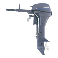
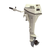
F80 F100
IGNITION SYSTEM
Ignition firing order Cylinders #1
→
#3
→
#4
→
#2
Ignition timing Degree 5˚ ATDC ~ 25˚ BTDC
Lighting coil output peak voltage
(W – W)
at 400 r/min (cranking) V 7.1
at 1,500 r/min V 15
at 3,500 r/min V 18
Lighting coil resistance (W – W)
Ω
@
20
˚C (68 ˚F) 0.32 ~ 0.48
Pick-up coil output peak voltage
(W/B – B, W/R – B)
at 400 r/min (cranking) V 2.7
at 1,500 r/min V 7
at 3,500 r/min V 11
Pick-up coil resistance
(W/B – B, W/R – B)
Ω
@
20
˚C (68 ˚F) 445 ~ 545
CDI unit output peak voltage
(B/W – B, B/O – B)
at 400 r/min (cranking) V 125
at 1,500 r/min V 130
at 3,500 r/min V 130
Spark plug lead assy. resistance
Cylinder #1 lead k
Ω
@
20 ˚C (68 ˚F) 4.5 ~ 10.7
Cylinder #2 lead k
Ω
@
20
˚C (68 ˚F) 3.3 ~ 8.0
Cylinder #3 lead k
Ω
@
20
˚C (68 ˚F) 3.7 ~ 8.9
Cylinder #4 lead k
Ω
@
20
˚C (68 ˚F) 4.3 ~ 10.2
Ignition coil resistance
Primary
Ω
@
20
˚C (68 ˚F) 0.078 ~ 0.106
Secondary k
Ω
@
20
˚C (68 ˚F) 3.5 ~ 4.7
IGNITION CONTROL SYSTEM
Oil pressure switch (on/off) kPa (kg/cm
2
, psi) 15 (0.15, 2.13)
Engine temperature sensor
resistance
at -20 ˚C (-4 ˚F) k
Ω
15.5
at 0 ˚C (32 ˚F) k
Ω
5.79
at 20 ˚C (68 ˚F) k
Ω
2.45
at 40 ˚C (104 ˚F) k
Ω
1.50
at 60 ˚C (140 ˚F) k
Ω
0.59
CHARGING SYSTEM
Rectifier/regulator output peak
voltage (R – B)
at 1,500 r/min V 14
at 3,500 r/min V 18