NOTE:-------------
Cylinder porting,
combustion
chamber
com-
pression. ignition
timing,
muffler
design. and
carburetor size and
component
selection are
all balanced
to
achieve
optimum
perfor-
mance. However. variations in temperature,
humidity
and altitude,
to
name a few.
will
affect
carburetion and consequently, engine
performance.
The
following
list
gives each
of
the
major
components
of
the
carburetor
that
can be
readily changed in order
to
modify
carburetor
performance
if
required.
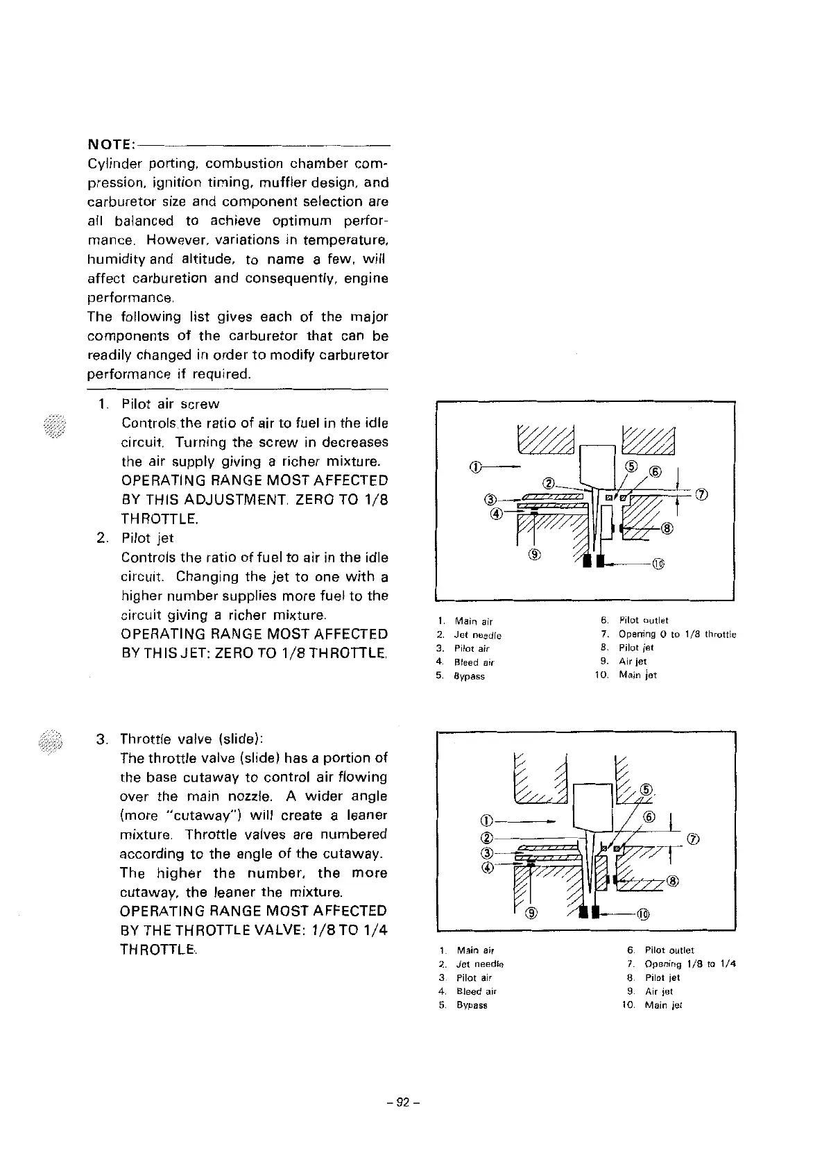
1.
Pilot air screw
Controls
the
ratio
of
air to fuel in the idle
circuit. Turning the
screw
in decreases
the air supply giving a richer mixture.
OPERATING RANGE
MOST
AFFECTED
BY
THIS
ADJUSTMENT.
ZERO TO
1/8
THROTTLE.
2. Pilot
jet
Controls the ratio
of
fuel
to
air in the idle
circuit. Changing the
jet
to
one
with
a
higher
number
supplies more fuel
to
the
circuit giving a richer mixture.
OPERATING RANGE
MOST
AFFECTED
BY
THIS JET: ZERO TO
1/8
THROITLE.
3. Throttle valve (slide):
The
throttle
valve
(slide) has a
portion
of
the
base
cutaway
to
control air
flowing
over
the main nozzle. A
wider
angle
(more
"cutaway")
will
create a leaner
mixture.
Throttle
valves are numbered
according
to
the angle
of
the
cutaway.
The
higher
the
number,
the
more
cutaway. the leaner the mixture.
OPERATING RANGE
MOST
AFFECTED
BY
THE THROTTLE VALVE:
1/8
TO
1/4
THROTTLE.
-92
-
1
Main
air
2.
Jet
needle
3. Pilot air
4.
Bleed air
5.
Bypass
1.
Main
aJr
2.
Jet
needle
3 Pilot air
4. Bleed air
5. Bypass
6 Pilot
outlet
7. Opening O to
1/8
throttle
8. Pilot jet
9.
Air
jet
10. Main Jet
6.
Pilot
outlet
7. Opening
1/8
to
1/4
8 Pilot
jet
9.
Air
jet
10.
Main
jet



 To Next Page