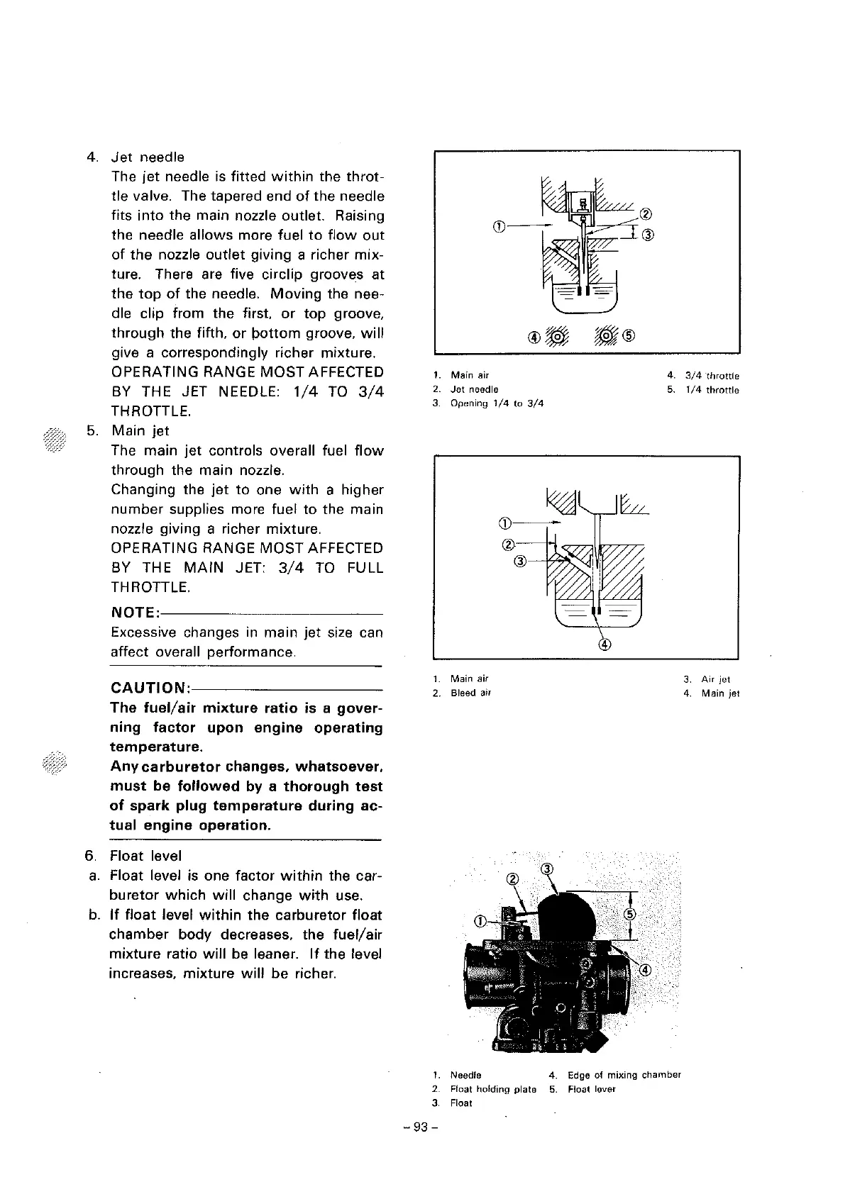
4.
Jet
need
le
The
jet
needle is fitted
within
the
throt-
tle valve. The tapered end
of
the
needle
fits
into
the main nozzle outlet. Raising
the needle
allows
more fuel
to
flow
out
of
the
nozzle
outlet
giving
a richer
mix-
ture. There are five circlip grooves
at
the
top
of
the needle.
Moving
the nee-
dle clip from
the
first
or
top
groove,
through
the fifth,
or
pottom
groove,
will
give a correspondingly richer mixture.
OPERATING RANGE
MOST
AFFECTED
BY THE JET NEEDLE:
1/4
TO
3/4
THROTTLE.
5.
Main
jet
The main
jet
controls overall fuel
flow
through the main nozzle.
Changing the
jet
to
one
with
a higher
number
supplies more fuel to the main
nozzle giving a richer mixture.
OPERATING RANGE
MOST
AFFECTED
BY THE
MAIN
JET:
3/4
TO
FULL
THROTTLE.
NOTE:------------
Excessive changes in
main
jet
size can
affect overall performance.
CAUTION:----------
The
fuel/air
mixture
ratio
is a
gover-
ning
factor
upon
engine
operating
temperature.
Any
carburetor
changes,
whatsoever,
must
be
followed
by
a
thorough
test
of
spark
plug
temperature
during
ac-
tual
engine
operation.
6.
Float level
a.
Float level is one factor
within
the car-
buretor
which
will
change
with
use.
b.
If
float
level
within
the
carburetor
float
chamber
body
decreases, the
fuel/air
mixture
ratio
will
be leaner.
If
the level
increases,
mixture
will
be
richer.
1.
Main
air
2.
Jet
needle
3. Opening
1/4
to
3/4
1.
Main air
2. Bleed air
(j)---
®----M
@
4.
3/4
·throttle
5. 1 I 4
throttle
3.
Air
jet
4.
Main
jet
1.
Needle
4. Edge of mixing chamber
2. Float holding plate 5. Float lever
3.
Float
-93
-



 To Next Page