13
MOX6/MOX8
Fig.4(図 4)
Fig.5(図 5)
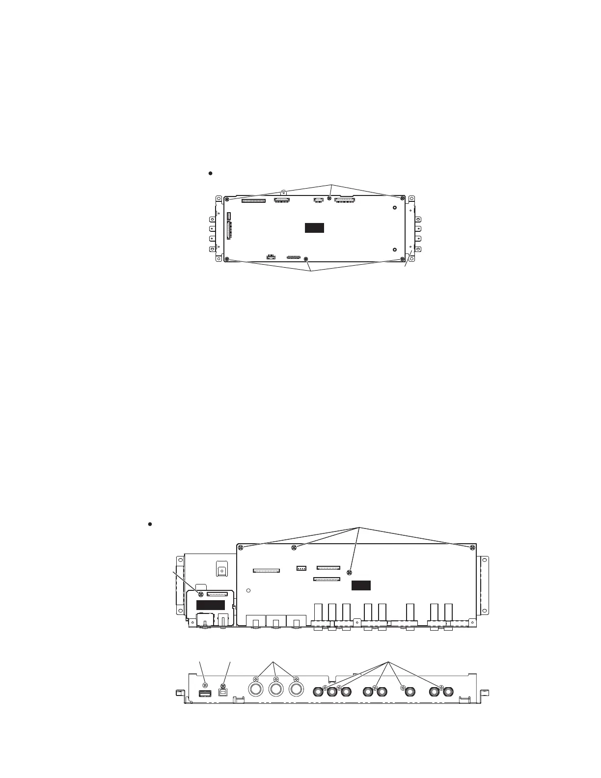
3. DM Circuit Board
(Time required: About 5 minutes)
3-1 Remove the lower case assembly. (See procedure 1.)
3-2 Remove the DM sub assembly. (See procedure 2.)
3-3 Remove the six (6) screws marked [30c]. The DM circuit
board can then be removed. (Fig.4)
3. DM シート(所要時間 : 約 5 分)
3-1 下ケース Ass'y を外します 。(1 項参照)
3-2 DM サブ Ass'y を外します 。(2 項参照)
3-3 [30c] のネジ 6 本を外して、DM シートを外します 。
(図 4)
7RS9LHZ!
上から見た図!
'06XE$VVHPEO\
(DMサブAss'y)
'0
>F@
>F@
'0)L[WXUH
(DM固定金具)
4. JK Circuit Board
(Time required: About 6 minutes)
4-1 Remove the lower case assembly. (See procedure 1.)
4-2 Remove the eight (8) screws marked [20dA] and the four
(4) screws marked [20dB]. The JK circuit board can then
be removed. (Fig.5)
5. USB Circuit Board
(Time required: About 5 minutes)
5-1 Remove the lower case assembly. (See procedure 1.)
5-2 Remove the screw marked [20e], the screw marked [20dC]
and the screw marked [20dD]. The USB circuit board can
then be removed. (Fig.5)
4. JK シート(所要時間 : 約 6 分)
4-1 下ケース Ass'y を外します 。(1 項参照)
4-2 [20dA] のネジ 8 本と [20dB] のネジ 4 本を外して、JK
シートを外します 。(図 5)
5. USB シート(所要時間 : 約 5 分)
5-1 下ケース Ass'y を外します 。(1 項参照)
5-2 [20e] のネジ 1 本、[20dC] のネジ 1 本と [20dD] のネ
ジ 1 本を外して、USB シートを外します 。(図 5)
7RS9LHZ!上から見た図!
5HDU9LHZ!後ろから見た図!
-.6XE$VVHPEO\
(JKサブAss'y)
86%
-.
>G'@
>G%@
>G&@ >H@ >G$@ >G$@
 Loading...