28
MOX6/MOX8
10-2 GHL88L Circuit Board
Tighten the six (6) screws marked [260A] to fi x the
GHL88L circuit boards. (Fig.13)
10-3 GHL88M Circuit Board
Connect the FFC cable to CN2 of the GHL88M circuit
board, attach the fi lament tape. (Fig.15)
Pass the end of the cable into the through hole in the
frame and pull it out from its outlet. (Fig.15)
Tighten the seven (7) screws marked [260B] to fi x the
GHL88M circuit board. (Fig.13)
10-4 GHL88H Circuit Board
Tighten the fi ve (5) screws marked [260C] to fi x the
GHL88H circuit board. (Fig.13)
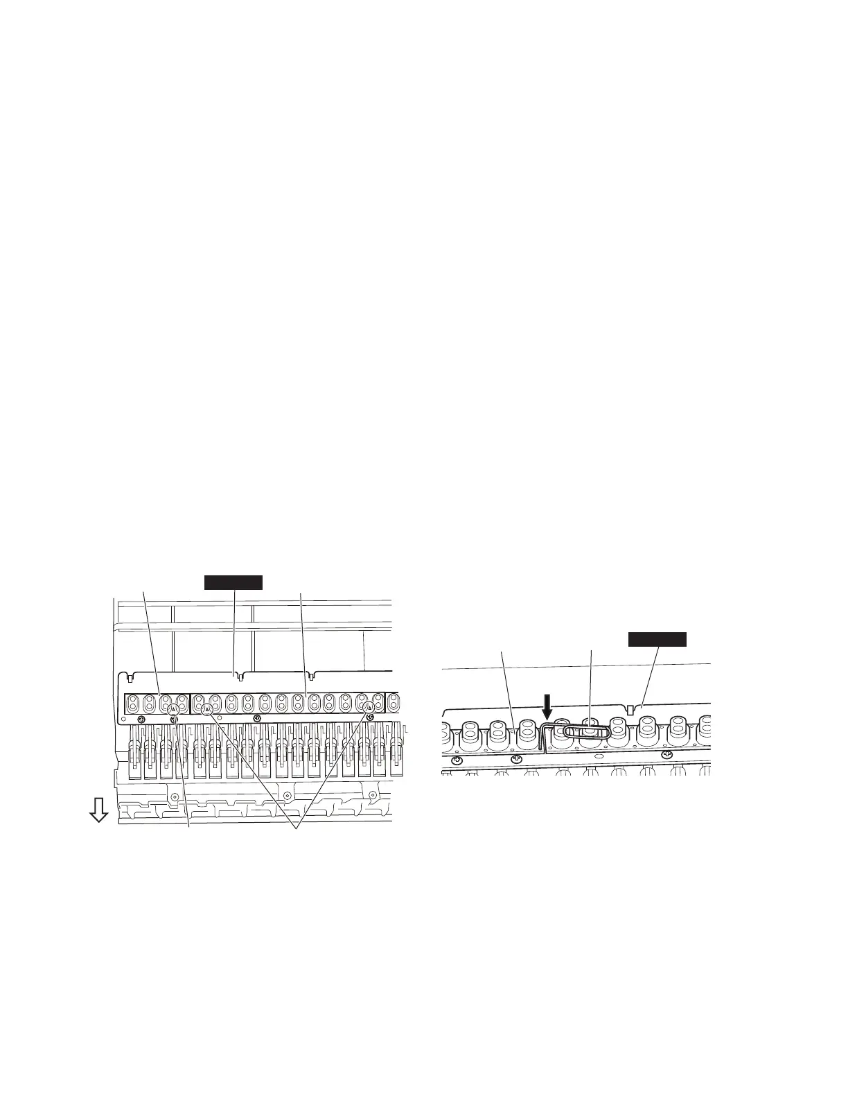
10-5 Rubber Contact
Note that the rubber contact has s specifi c installation
direction. Be careful not to install it in the wrong
direction.
* A triangle mark (
△
) on the rubber contact must face the
front. (Fig.19)
To prevent looseness of the rubber contact, fi t it securely
in place using a clip or similar object. (Fig.20)
10-2 GHL88L シート
GHL88L シートを取り付け、[260A] のネジ 6 本で固
定します。(図 13)
10-3 GHL88M シート
FFC ケーブルを GHL88M シートの CN2 に差し込み、
フィラメントテープを貼り付けます。(図 15)
ケーブルの先をフレームの通し穴に通して、抜き口
から引き出します。(図 15)
GHL88M シートを取り付け、[260B] のネジ 7 本で固
定します。(図 13)
10-4 GHL88H シート
GHL88H シートを取り付け、[260C] のネジ 5 本で固
定します。(図 13)
10-5 接点ゴム
接点ゴムには、取り付けの向きが決まっています。
接点ゴムを逆に取り付けないように注意してくださ
い。
※ 接点ゴムの三角マーク(△)がフロント側になることを確
認します。(図 19)
接点ゴムの浮きがないように、クリップ等で接点ゴ
ムを基板にはめ込みます。(図 20)
*+//
7ULDQJOH0DUN
(三角マーク)
)URQW
(フロント)
5XEEHU&RQWDFW
(接点ゴム)
5XEEHU&RQWDFW
(接点ゴム)
7ULDQJOH0DUN
(三角マーク)
&OLS
(クリップ)
*+//
5XEEHU&RQWDFW
(接点ゴム)
Fig.19
(図 19)
Fig.20
(図 20)

 Loading...