15
MOX6/MOX8
7. Crystal Display, LCD Circuit Board
(Time required: About 5 minutes each)
7-1 Remove the upper case assembly. (See procedure 1.)
7-2 Remove the LCD assembly. (See procedure 6.)
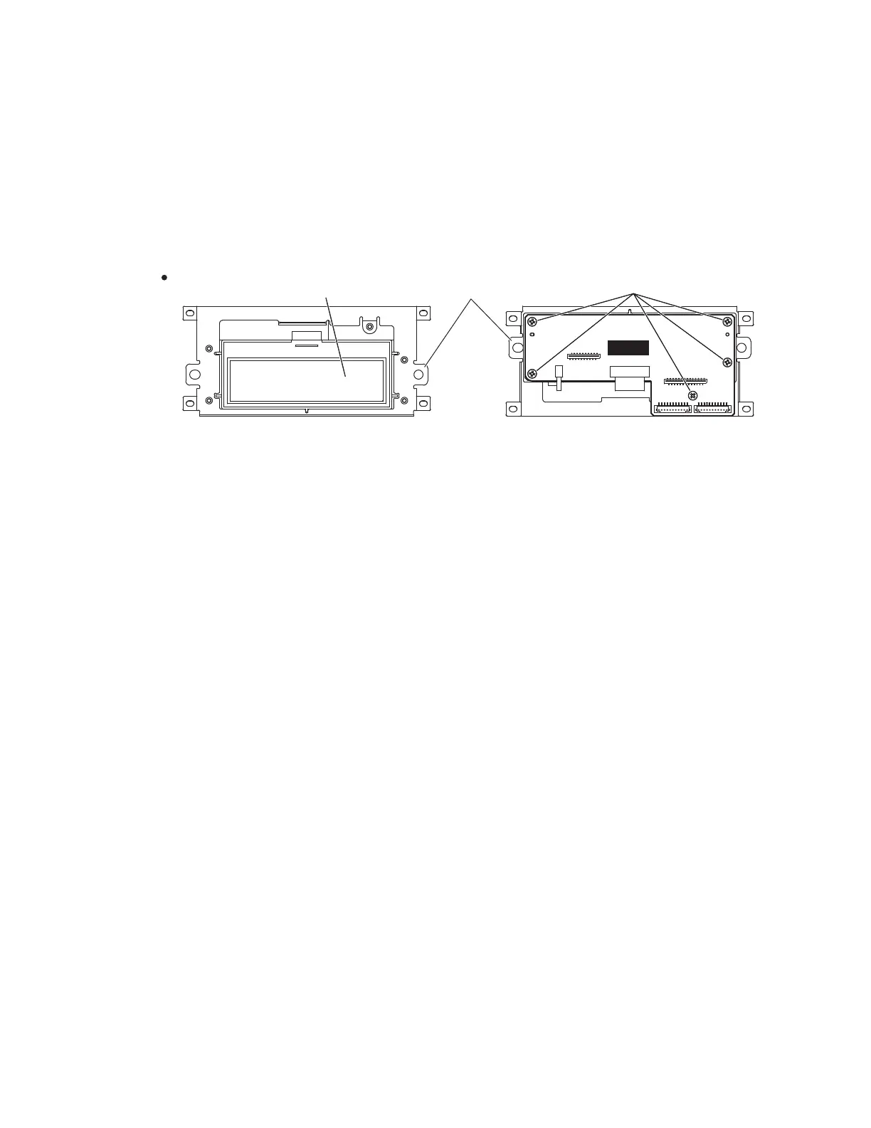
7-3 Remove the fi ve (5) screws marked [40d]. The crystal
display and LCD circuit board can then be removed from
the LCD fi xture. (Fig.8)
7. 液晶ディスプレイ、LCD シート
(所要時間 : 各約 5 分)
7-1 上ケース Ass'y を外します 。(1 項参照)
7-2 LCDAss'y を外します 。(6 項参照)
7-3 [40d] のネジ 5 本を外して、液晶ディスプレイ、LCD
シートを LCD 取付金具から外します 。(図 8)
Fig.8(図 8)
8. 16NW-C61 鍵盤 Ass'y の分解
8-1 下ケース Ass'y を外します 。(1 項参照)
8-2 白鍵、黒鍵
8-2-1 白鍵、黒鍵は、左側から 1 オクターブ単位のセット
になっていて、全部で 5 セットあります。C6 鍵は、
白鍵 1 個のみです。(図 9)
8-2-2 セットのものは、[120A] のネジ 4 本づつ外してそれ
ぞれ 1 セット分の白鍵、黒鍵を外します。(図 9)
この時、黒鍵の後ろ側にある 2 つのフックを上方向
に外し、白鍵・黒鍵を少し手前に引きながら持ち上
げます。(図 10)
8-2-3 C6 の白鍵は [120B] のネジ 1 本を外し、8-2-2 項の様
にフックを外して手前に引きながら外します。(図 9、
図 10)
8-3 接点ゴム
8-3-1 外そうとする接点ゴムに対応した白鍵・黒鍵を外し
ます。(図 9)
8-3-2 それぞれの接点ゴムを外します。(図 9)
8. Disassembling 16NW-C61 Keyboard
Assembly
8-1 Remove the lower case assembly. (See procedure 1.)
8-2 White Keys and Black Keys
8-2-1 White and black keys for one octave unit are integrated
as a set. There are fi ve sets in total. Only the C6 white
key, unlike the other keys, is not integrated in a set. (Fig.9)
8-2-2 To remove a set, remove the four (4) screws marked
[120A]. The white and black keys in the set can then be
removed. (Fig.9)
When removing, unfasten the two (2) hooks at the back
of the black keys upward, and lift the white and black
keys while pulling them toward you a little. (Fig.10)
8-2-3 To remove the white key C6, remove the screw marked
[120B], unhook as described in Procedure 8-2-2, and pull
out toward you. (Fig.9, Fig.10)
8-3 Rubber Contact
8-3-1 Remove the white and black keys corresponding to the
rubber contacts to be removed. (Fig.9)
8-3-2 Remove the rubber contacts. (Fig.9)
7RS9LHZ!上から見た図! %RWWRP9LHZ!下から見た図!
/&'$VVHPEO\
(LCDAss'y)
>G@
/&'
&ULVWDO'LVSOD\
(液晶ディスプレイ)
/&')L[WXUH
(LCD取付金具)
 Loading...