24
MOX6/MOX8
Fig.12
(図 12)
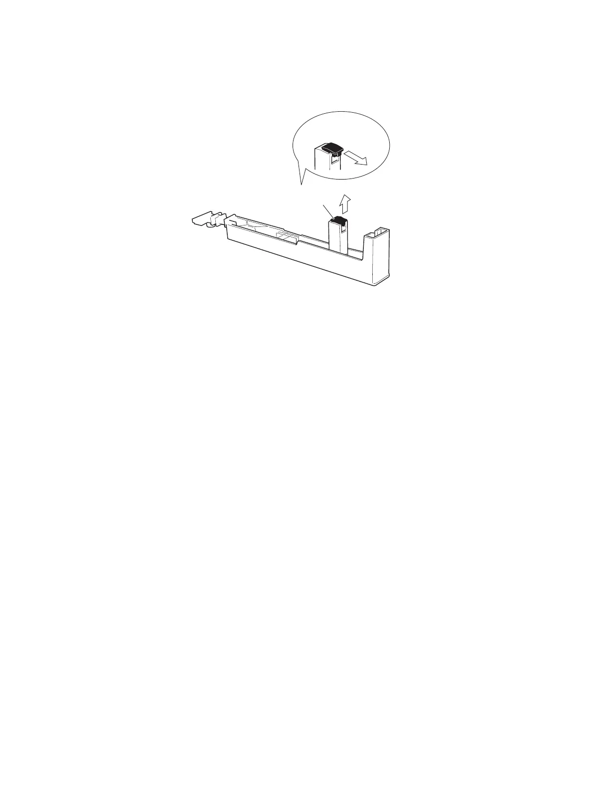
9-4 Actuate Rubber
Remove the actuate rubber. (Fig.12)
9-4 駆動ラバー
白鍵(黒鍵)の駆動ラバーを外します。(図 12)
$FWXDWH5XEEHU
(駆動ラバー)
5HPRYHLQWKLVZD\
(取り出す)
9-5 Rubber Contact
Remove the black and white key assemblies for two
octaves related to the subject rubber contact.
The rubber contact can then be removed. (Fig.13, Fig.14)
* Note that the rubber contact has a specifi c installation
direction.
* One rubber contact fi ts for C#-C (for C-B keys).
9-6 GHL88L Circuit Board
Remove the black and white key assemblies (A1-B2). (See
procedure 9-1.)
Remove the six (6) screws marked [260A]. The GHL88L
circuit board can then be removed. (Fig.13)
9-7 GHL88M Circuit Board
Remove the black and white key assemblies (C1-B5).
(See procedure 9-1.)
Remove the seven (7) screws marked [260B]. The
GHL88M circuit board can then be removed. (Fig.13)
Detach the fi lament tape and disconnect the FFC cable.
(Fig.15)
9-8 GHL88H Circuit Board
Remove the black and white key assemblies (C5-C7).
(See procedure 9-1.)
Remove the fi ve (5) screws marked [260C]. The
GHL88H circuit board can then be removed. (Fig.13)
9-5 接点ゴム
該当する接点ゴムの 2 オクターブ分の白鍵 Ass'y/ 黒
鍵 Ass'y を外して、接点ゴムを外します。
(図 13, 図 14)
※ 接点ゴムには、向きがあります。
※ 接点ゴムは、C# 〜 C の一連です。(キーは C 〜 B)
9-6 GHL88L シート
A-1 〜 B2 までの白鍵 Ass'y/ 黒鍵 Ass'y を外します。
(9-1 項参照)
[260A] のネジ 6 本を外して、GHL88L シートを外し
ます。(図 13)
9-7 GHL88M シート
C1 〜 B5 までの白鍵 Ass'y/ 黒鍵 Ass'y を外します。
(9-1 項参照)
[260B] のネジ 7 本を外して、GHL88M シートを外し
ます。(図 13)
フィラメントテープをはがして、FFC ケーブルを抜
き取ります。(図 15)
9-8 GHL88H シート
C5 〜 C7 までの白鍵 Ass'y/ 黒鍵 Ass'y を外します。
(9-1 項参照)
[260C] のネジ 5 本を外して、GHL88H シートを外し
ます。(図 13)
 Loading...