17
MOX6/MOX8
8-4 61L Circuit Board (MK-L)
(Time required: About 7 minutes)
8-4-1 Remove the white and black keys from C1 to B3.
(See Fig.9 and Procedure 8-2.)
8-4-2 Remove the four (4) screws marked [100A] and the eight
(8) screws marked [110A]. The 61L circuit board (MK-L)
can then be removed. (Fig.9)
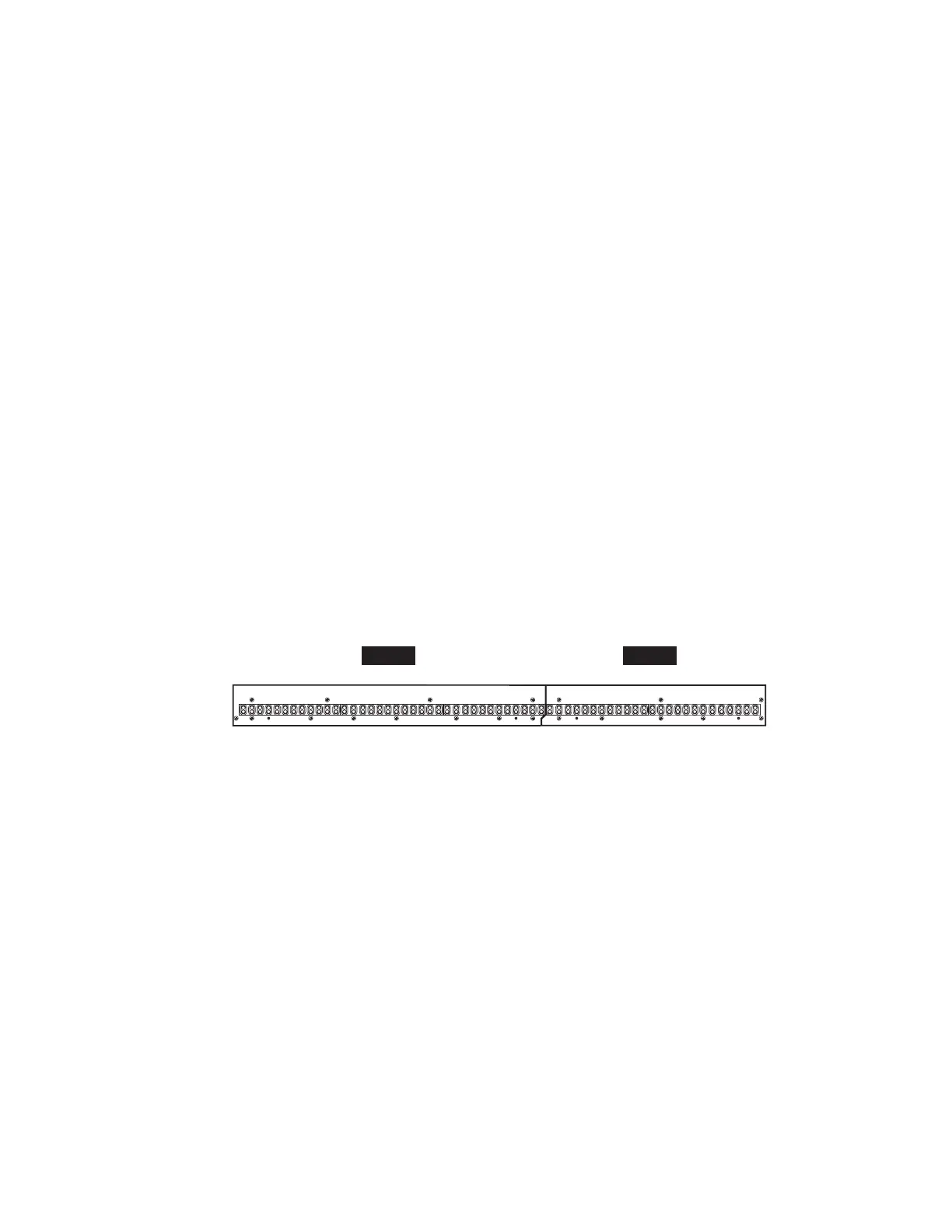
* When installing the 61L circuit board (MK-L), tighten the
screws 1 through 12 in numerical order as shown in the fi gure
"61L" in Fig.11. (Fig.11)
* As for the screw marked [110A] at the location of "F", it is
tightened together with a GND terminal. (Fig.9)
8-5 61H Circuit Board (MK-H)
(Time required: About 6 minutes)
8-5-1 Remove the white and black keys from C4 to C6.
(See Fig.9 and Procedure 8-2.)
8-5-2 Remove the three (3) screws marked [100B] and the fi ve
(5) screws marked [110B]. The 61H circuit board (MK-H)
can then be removed. (Fig.9)
* When installing the 61H circuit board (MK-H), tighten the
screws 1 through 8 in numerical order as shown in the fi gure
"61H" in Fig.11. (Fig.11)
* As for the screw marked [100B] at the location of "G", it is
tightened together with a GND terminal. (Fig.9)
8-4 シート 61L(MK-L)(所要時間:約 7 分)
8-4-1 C1 〜 B3 の白鍵・黒鍵を外します。(図 9、8-2 項参照)
8-4-2 [100A] のネジ 4 本と [110A] のネジ 8 本を外し、シー
ト 61L(MK-L)を外します。(図 9)
※ シート 61L(MK-L)を取り付ける時は、図 11 のシート
61L図の番号1〜12の順にネジを締めて下さい。(図 11)
※ "F" の位置の [110A] のネジは、GND 端子と共締めされて
います。(図 9)
8-5 シート 61H(MK-H)(所要時間:約 6 分)
8-5-1 C4 〜 C6 の白鍵・黒鍵を外します。(図 9、8-2 項参照)
8-5-2 [100B] のネジ 3 本と [110B] のネジ 5 本を外し、シー
ト 61H(MK-H)を外します。(図 9)
※ シート 61H(MK-H)を取り付ける時は、図 11 のシート
61H図の番号1〜8の順にネジを締めて下さい。(図 11)
※ "G" の位置の [100B] のネジは、GND 端子と共締めされて
います。(図 9)
Fig.11(図 11)
+/
 Loading...