29
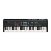
MOX6/MOX8
Fig.21
(図 21)
Fig.22
(図 22)
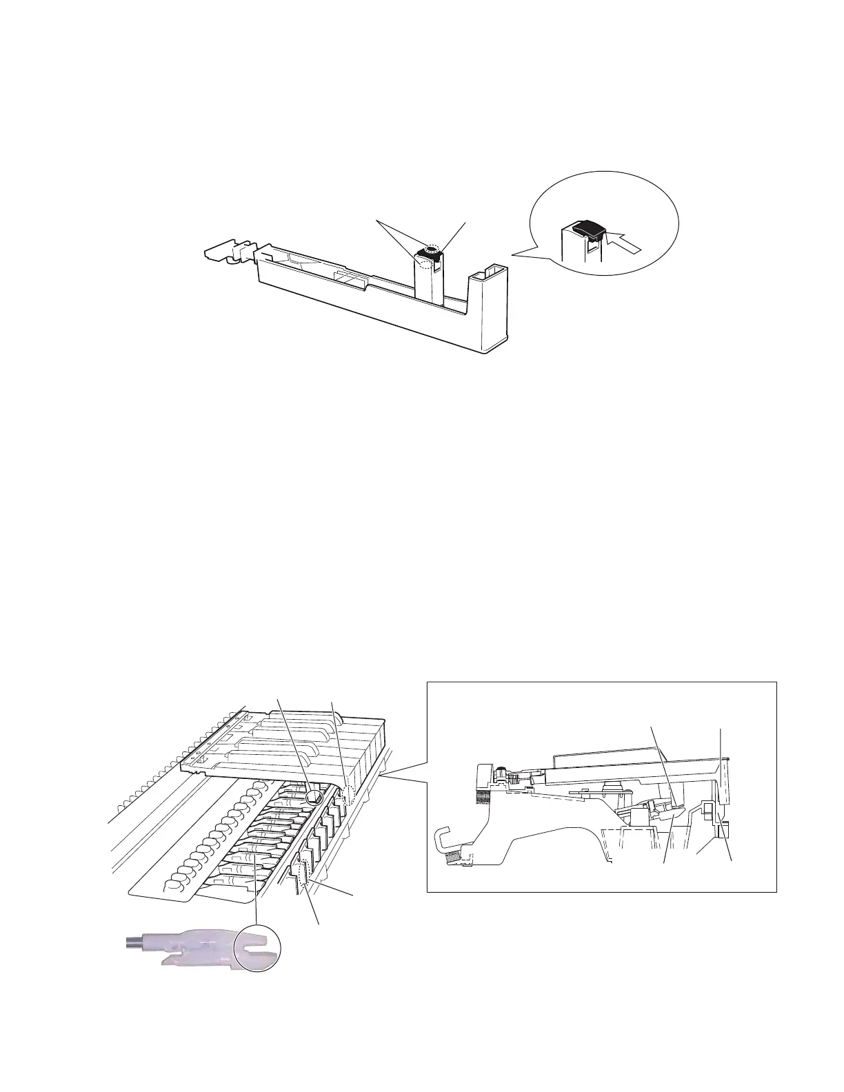
10-6 Actuate Rubber
After applying grease to top and bottom faces of the
actuate rubber, fi t it to the white key(black key). (Fig.21)
10-6 駆動ラバー
駆動ラバーの上下にグリスを塗布後、白鍵(黒鍵)
に駆動ラバーをはめ込みます。(図 21)
)LWLQWKLVZD\
(はめ込む)
$FWXDWHUXEEHU
(駆動ラバー)
$SSO\JUHDVH
(グリス塗布)
10-7 White key assembly and black key
assembly
After applying grease to the key guide, install the white
key assembly/black key assembly.
At this time, check to make sure that the key guide of the
key frame and inside slit at the front of white key as well
as the contact arm of the hammer and actuate rubber of
the white key assembly/black key assembly are installed
properly. (Fig.22)
Use the four (4) screws marked [270A] to fi x 1 octave
white key assembly/black key assembly. (Fig.10)
10-8 Use the two (2) screws marked [270B] to fi x the A-1 to
B-1 keys. (Fig.10)
10-9 Use a screw marked [270C] to fi x the C7 key. (Fig.10)
10-7 白鍵 Ass'y、黒鍵 Ass'y
キーガイドにグリス塗布後、白鍵 Ass'y/ 黒鍵 Ass'y
を取り付けます。
この時、鍵盤フレームのキーガイドと白鍵前部の内
側スリット、ハンマーの接点アームと白鍵 Ass'y/ 黒
鍵 Ass'y の駆動ラバーがはめ込まれていることを確
認してください。(図 22)
1 オクターブの白鍵 Ass'y/ 黒鍵 Ass'y は、[270A] の
ネジ 4 本で固定します。(図 10)
10-8 A-1 〜 B-1 鍵は、[270B] のネジ 2 本で固定します。
(図 10)
10-9 C7 鍵は、[270C] のネジ 1 本で固定します。(図 10)
&RQWDFW$UP
(接点アーム)
+DPPHU
(ハンマー)
6OLW
(スリット)
6OLW
&RQWDFW$UP
(接点アーム)
.H\*XLGH
(キーガイド)
.H\*XLGH
(キーガイド)
$FWXDWH5XEEHU
(駆動ラバー)
$SSO\JUHDVH
(グリス塗布)
$FWXDWH5XEEHU
(駆動ラバー)
6LGHYLHZ!横から見た図!
 Loading...