121110987654321
121110987654321
P
O
N
M
L
K
J
H
G
F
E
D
C
B
A
QQ
P
O
N
M
L
K
J
II
H
G
F
E
D
C
B
A
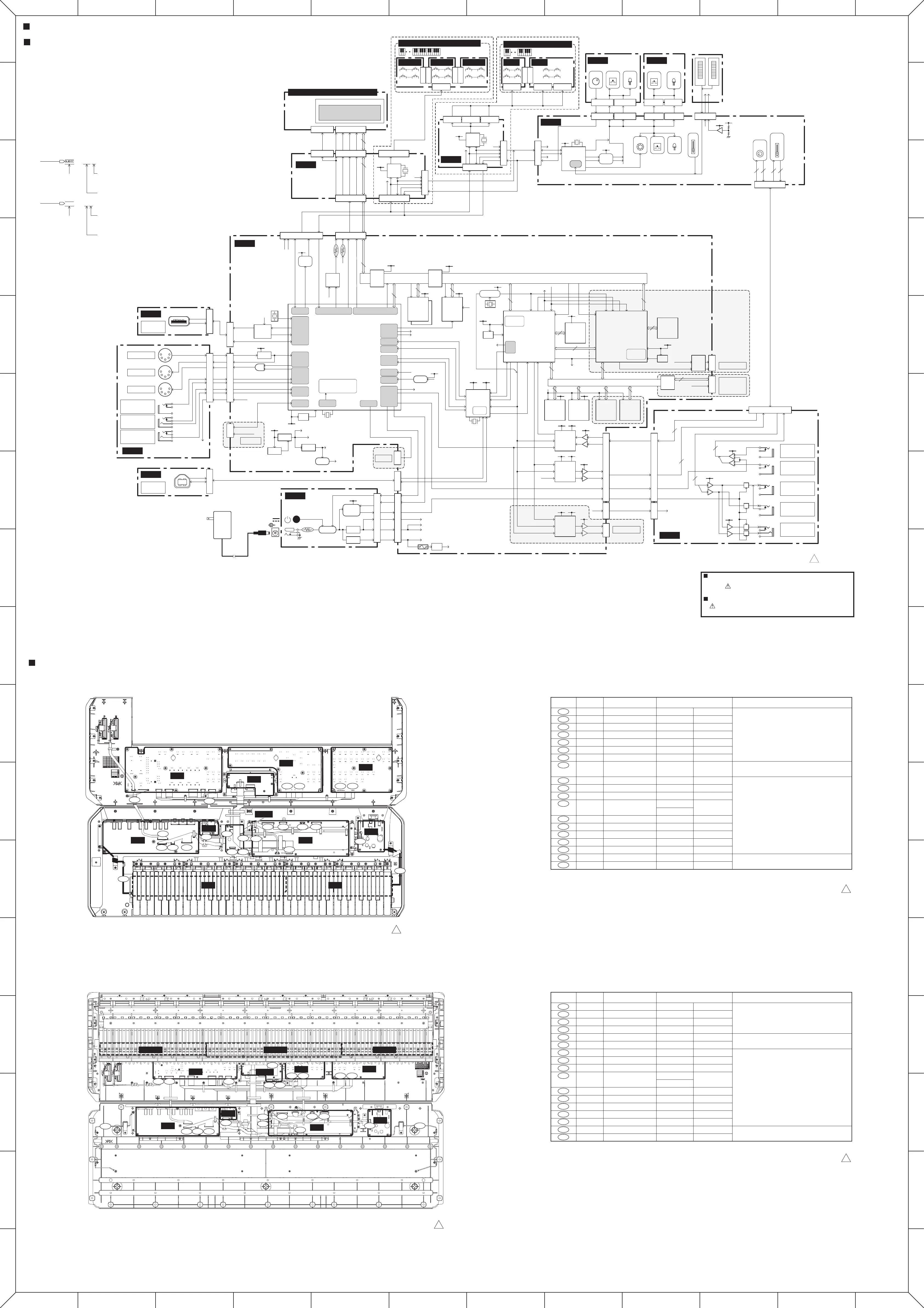
MOX6/MOX8 CIRCUIT BOARD LAYOUT & WIRING
(ユニットレイアウト及び結線図)
MOX6/MOX8 BLOCK DIAGRAM(ブロックダイアグラム)
<Page 1>
MOX6/MOX8
MOX6/MOX8
MOX6/MOX8
CONTENTS
MOX6/MOX8 OVERALL CIRCUIT DIAGRAM
(総回路図索引)
61H(MOX6) ........................... 8
61L(MOX6)............................ 8
DM 1/3................................... 2
DM 2/3................................... 3
DM 3/3................................... 4
GHL88H(MOX8).................... 8
GHL88L(MOX8) .................... 8
GHL88M(MOX8) ................... 8
JK .......................................... 5
KEY-IF(MOX6) ...................... 7
LCD ....................................... 7
PNA ....................................... 6
PNB ....................................... 6
PNC....................................... 6
PS.......................................... 7
USB ....................................... 7
<Page5 J-8>
Notation for Circuit Diagrams
1. How to identify inter-circuit connectors.
Ex.1
Signal name
The number indicates the destination page.
This indicates the location of the counter inter-circuit connector.
(The alphabet indicates horizontal direction and the number indicates vertical direction.)
2:G8
Ex.2 (DM circuit diagram)
Signal name
The number indicates the destination page (DM2).
This indicates the location of the counter inter-circuit connector.
(The alphabet indicates vertical direction and the number indicates horizontal direction.)
LRES
Destination
(行き先)
Remarks
(備考)
(WV71230)
(WV71250)
(WW12790)
(WW12820)
(WV71300)
(WV71310)
(WV71320)
WY675500
(WV71040)
(WV71070)
(WV71080)
(WY50190)
(WV71100)
(WV71270)
(WV71130)
(WV71150)
(WV71160)
(WW44370)
(WW44370)
Wiring Assembly PNC1
Wiring Assembly PNC2
Wiring Assembly PNB1
Wire Assembly PNB2
Wiring Assembly KEY6-R1
Wiring Assembly KEY6-R2
Wiring Assembly KEY6-R3
Flexible Flat Cable LCD-PE
Wiring Assembly VDD
Wiring Assembly AVDD
Wiring Assembly ANA-S
Wiring Assembly USB-PE
Wiring Assembly MIDI
Wiring Assembly E-BUS2
Wiring Assembly E-BUS1
Wiring Assembly VR-S
Wiring Assembly WHEEL
Wiring Assembly GND2
Wiring Assembly GND2
Match the edge mark of wire to the pin 1 mark [ ] of PCB.
束線のエッジマークを基板上の1pin指標[ ]側に。
Match the conductor side of FFC to contact side of connector.
FFCの導体面をコネクタの接点側に。
Match the concavity and convexity between connectors.
コネクタ同士の凹凸を合わせる。
Mounted with screw.
ネジと共締め。
PNA CN204
PNA CN203
PNA CN205
PNA CN206
KEY-IF CN704
KEY-IF CN705
KEY-IF CN706
LCD CN801
PS CN501
JK CN003
JK CN002
USB CN902
JK CN101
KEY-IF CN702
PNA CN601
PNA CN202
PNA CN603
DM shield
JK SUB Assembly
PNC CN402
PNC CN401
PNB CN301
PNB CN302
61H CN1
61L CN5
61H CN2
DM CN300
DM CN2
DM CN3
DM CN901
DM CN105
DM CN800
DM CN102
DM CN104
KEY-IF CN701
JK CN001
-
61H -
61L -
Part No.
(部品番号)
Assembly
(束線)
Location
(ロケーション)
The parts that correspond to the number with ( ) are not prepared as service parts.
(部品番号が()で囲まれた部品は、サービス部品としては用意されていません。)
(部品番号が()で囲まれた部品は、サービス部品としては用意されていません。)
WH401
WH402
WH301
WH302
110
130
120
H120
H10
H40
H50
H60
H70
H100
W20
W10
80
H20
H20
Destination
(行き先)
Remarks
(備考)
(WV71230)
(WV71250)
(WW12790)
(WW12820)
WW195200
WY675500
(WV71040)
(WV71070)
(WV71080)
(WY50190)
(WV71100)
(WV71130)
(WV71130)
(WV71150)
(WV71160)
(WW44360)
(WW44360)
Wiring Assembly PNC1
Wiring Assembly PNC2
Wiring Assembly PNB1
Wire Assembly PNB2
Flexible Flat Cable (GHL)
Wiring Assembly LCD-PE
Wiring Assembly VDD
Wiring Assembly AVDD
Wiring Assembly ANA-S
Wiring Assembly USB-PE
Wiring Assembly MIDI
Wiring Assembly E-BUS1
Wiring Assembly E-BUS1
Wiring Assembly VR-S
Wiring Assembly WHEEL
Wiring Assembly GND1
Wiring Assembly GND1
Match the edge mark of wire to the pin 1 mark [ ] of PCB.
束線のエッジマークを基板上の1pin指標[ ]側に。
Match the conductor side of FFC to contact side of connector.
FFCの導体面をコネクタの接点側に。
Match the concavity and convexity between connectors.
コネクタ同士の凹凸を合わせる。
Mounted with screw.
ネジと共締め。
PNA CN204
PNA CN203
PNA CN205
PNA CN206
LCD CN806
LCD CN801
PS CN501
JK CN003
JK CN002
USB CN902
JK CN101
LCD CN804
PNA CN601
PNA CN202
PNA CN603
PS -
JK SUB Assembly
PNC CN402
PNC CN401
PNB CN301
PNB CN302
GHL88M CN2
DM CN300
DM CN2
DM CN3
DM CN901
DM CN105
DM CN800
DM CN102
DM CN104
LCD CN805
JK CN001
-
Lower case shield
Lower case shield
Part No.
(部品番号)
Assembly
(束線)
Location
(ロケーション)
The parts that correspond to the number with ( ) are not prepared as service parts.
WH401
WH402
WH301
WH302
2
H90
H10
H20
H30
H40
H50
W10
W10
W20
80
H70
H70
61L
PNA
• MOX6 • MOX6
• MOX8 • MOX8
PNB
LCD
PNC
PNA
GHL88L
PNB
PNC
61H
JK DM
JK
DM
PS
GHL88M GHL88H
PS
USB
LCD
2NC-WU82180-1 1
2NC-WV38850-1 1
2NC-WV38850-3 1
2NC-WU82180-3 1
KEY-IF
USB
WH401 WH402WH301
W10
80
H20
H20
H50 H40 H70
H60
130 120
H120
110
100
H10 H100 H60 H70
H10
H50
H70
H30 H20 H50
H40
H30
H20
H10
H90
W10
W2080 W10
W10
H40
2
H50
H10
H70
W20
WH302
WH401 WH402WH301 WH302
CPU
SWX02
16.9344MHz
UART
USB
(Host)
ADC
I2C
JTAG
GPIO
SH-2A CPU Core
Internal: 135.4752MHz
Bus: 67.7376MHz
UART
PLL
DCDC +3.3D
+3.3A
+5D
Reset
Reset
3.0V
tD=50ms3.0V
tD=220us
RUN
/SRES
Delay
/LRES
+3.3D
Reg
+1.2D
/MUTE
MIDI-/OE
FOOTSW
SUS-INS
MIC/LIN
PWR
tD=1us
E-LKS
X801
X701
10,24
35
10,24
35
IC801-64P
8.38MHz
+5D
BK[*],MK[*]
+5D
+5D
E-Bus
/EIC
+5LED
BK[*],MK[*]
BK[*],MK[*]
E-PNS2a
8.38MHz
+5D
E-Bus
/EIC
+5D
+5LED
Driver
LA[*]
DA[*]
+5LED
ENCA
ENCB
S[*]
L[*]
D[*]
Encoder
ADC
Slider
SW LED
RD
ENCA
ENCB
D[*],S[*],L[*]
D[*],S[*],L[*]
AD0
Input
Gain
Master
Volume
AD1
AD2
+5D
+5D
+2.5V
SDRAM
16MB
(64Mbit x2)
CPU Bus (@67.7376MHz) 16bit
Buffer
Buffer
FlashROM
16Mbit
(128Mbit)
<Program>
/CS3
+3.3D
/CS0
/SRES
PRG-/WP
48MHz
TG
SWP51L
<Master>
SDRAM
16MB
(64Mbit x2)
16
TG
SWP51L
<Slave>
SDRAM
16MB
(64Mbit x2)
Wave Memory Bus
32bit
32bit
A-Bus
WaveROM
(H)
64MB
(512Mbit)
WaveROM
(L)
64MB
(512Mbit)
WaveROM
(H)
**MB
(**Mbit)
WaveROM
(L)
**MB
(**Mbit)
Buffer
Internal:
90.3168MHz
SWP-/IC
/WAIT
SYo
RFCLKi
/CS4
/CS5
/CS6
RFCLKi
SYi
/WAIT
SWP-/IC
22.5792MHz
1/2 Divider
11.2896MHz
SYSCK
+3.3D
Reg
+1.5D
+3.3D
Reg
+1.5D
DAC-DAT[2-4],S-WCK,S-SYSCK,S-BCK,DITO
A/D
AK5381
D/A
WM8740
+9V
SWP-/IC
/WAIT
+3.3D+5A
+9V
+3.3D
+5A
D/A
WM8740
+9V
+3.3D
+5A
ADC-DAT
Reg
+5A
SYSCK
M-BCK
M-WCK
DAC-DAT[1]
DAC-DAT[0]
DAC-DAT[0-1]
ADC-DAT
SYSCK
M-BCK
M-WCK
DAC-/IC
USB
Audio
Internal:
90.3168MHz
Internal:
48MHz
+3.3D
+5D
6MHz
Delay
+3.3D
/WAIT
/EIRQ
I2C Bus
SWP-/INT
16
USC-SDI[0]
USC-SDO[0-1]
SYSCK
SYi
U-WCK
DAC-/IC
DAC-/MUTE
I2C Bus
SYSCK
M-BCK
M-WCK
SYSCK
M-BCK
M-WCK
USC-TXD, USC-RXD
IRQ
USC-/INT
USC-/IC
USC-/IC
USC-FUL, USC-H/M
USC-/CN, USC-/SUS
GPIO
DAC-/IC
DAC-/MUTE
GPIO
IRQ
SWP-/INT
/WAIT
I2C
GPIO
SWP-/IC
DAC-/IC
DAC-/MUTE
8bit
DAC-/IC
DAC-/MUTE
Buffer
PC[0-7]
PD[0-7]
Fuse
A10kA10k
PolySW
Power SW
Control
DC IN 12V
ENCA
ENCB
+5D,+5LED
E-Bus,/EIC
+5D,+5LED
E-Bus,/EIC
ENCA
ENCB
+5D,+5LED
E-Bus,/EIC
/CS7
/CS0,/CS3
/CS4,/CS5
/CS6
BUS Controller
Hi Side
SW
+5D
Hi Side
SW
VBUS-EN
/OC
+5USB
+5USB
+5USB
Level
Convert
+5D
Photo
Coupler
+5D
MIDI-I
MIDI-O
GPIO
AN0
AN1
/LRES
Digital Out
Flash
Expansion
Module
JTAG
Analog Out
MIC/LIN
Input
Output
ANMUTE
+5USB
CN903
JK106
JK104
JK105
JK102
JK103
JK101
CN901
SW501
JK501
AC Adapter
USB TO
DEVICE
ANMUTE
/MUTE
PWR
+5LED
+5D
+9V
+3.3A
+3.3A
GPIO
GPIO
+9V
USB
USB
USBVBUS
USB
VBUS
USB
VBUS
USB TO
HOST
+9V
OUTPUT
L/MONO
OUTPUT
R
PHONES
+9V
+9V
Output
ANMUTE
MIC/LIN
A/D INPUT
L
A/D INPUT
R
+9V
MIC/LIN
Input
for Debug
No Mount
No Mount
No Mount
No Mount
No Mount
/SRES
WAVE-/WP
EXT-WAVE-/WP
WAVE-/WP
/SRES
EXT-WAVE-/WP
/CS7
LCD-/RES
+3.3D,+5LCD
+5D,+5LED
E-Bus,/EIC
ENCA
ENCB
AD0,AD1,AD2
+5D
2
2
2
2
2 2
2
2
OutputInput
STANDBY/ON SW
DM
USB 1/2
USB
PS
2/2
JK 1/2
JK 2/2
61L
LCD Unit (4.4 Inch 240 x 64 Dots)
61H
CN1-12P CN2-5P
CN3-12P
GHL88L
CN1-17P
CN1-17P
GHL88M
CN1-17P
GHL88H
CN2-27P
CN705-7P CN704-12P CN706-5P
CN3-17P
CN4-12P
CN5-7P
MOX6 16N Keyboard (61Keys)
MOX8 GHL Keyboard (88Keys)
LCD
BACK LIGHT
CN802-40P
CN801-22P
CN300-22PCN104-11P
CN804-11P
CN702-11P
CN206-11P
CN302-11P
CN205-8P
CN202-16P
CN301-8P
CN204-13P
CN402-13P
CN203-5P
CN603-5P
CN401-5P
CN805-11P
CN902-13P(1/2)CN902-13P(2/2)
CN800-5P
CN3-4P
CN105-6PCN102-15P
CN501-15P
CN2-15P
CN901-12P
CN003-4P
CN002-12P
CN101-15P
CN701-11P
CN601-11P
CN806-27PCN803-2P
+5LCD
+3.3D
LCD-/RES
+5L
(backlight)
/CS7
8
+3.3D
LCD-/RES
/CS7
8
+5LCD
ENCA
ENCB
ENCA
ENCB
MOX8 Only
MOX6 Only
BK[*],MK[*]
E-LKS
8.38MHz
+5D
+5D
+5D
E-Bus
/EIC
+5LED
ENCA
ENCB
KEY-IF
PNA
LCD
Monochrome
LED back light
- white back
PNB PNC
ENCA
ENCB
D[*],S[*],L[*]
SW LED
D[*],S[*],L[*]
MW
AD1 AD2
+5D 2.5V
PB
Encoder SW LED
LCD-/IC
+3.3D
LCD-ON
+5LCD
PolySW
/EIC
/EIC
E-Bus
ENCA
ENCB
+5D
+5LED
8
32
32
16
16
16
16
32
32
16
16
16
16
32
FOOTSW
SUS-INS
AN0
AN1
MIDI IN
MIDI THRU
MIDI OUT
FOOT SW
ASSIGNABLE
FOOT SW
SUSTAIN
FOOT
CONTROLLER
DCDC
Reg
+5D
+9V
+5LED
PWR
Mute
Control
VDC
+9V
/MUTE
ANMUTE
CN001-16P
28CA1-2001074132 1
12V
+
-
IC701-64P
IC601-64P
IC602-8P
VR202
EC301
VR203
X601
10,24
35
8
5
6
+3.3D
20
1,3,9,14
27,43,49
+3.3D
1,3,9,14
27,43,49
1
27,43
2,9,
21,37
5
43
+3.3D
43
6 7
8
8
9 8
+3.3D
43
+3.3D
14
4
1
1,2
5
1
1
5
5
5
3
1 3
8
4
4
IC110-5P
IC2-16P
IC101-5P
IC311-6P
IC106-5P
IC310-20P
IC103,104-54P IC312-56P
IC504-5P
IC102-14P
IC800-52P
IC401-54P
IC502-56P
IC911-16P
IC912-8P
IC0004-8P
TR002
TR001
TR005,006
TR003,004
8
8
IC0002-8P
IC0003-8P
8
IC904-8P
IC901-28P
IC907-3P
FZ900
IC507-56P
X800
X900
IC900-14P
+3.3D
20
+3.3D
14
IC308,309-20P
IC100-316P
IC400-388P
X102
IC3-5P
IC502-8P
IC503-3P
IC1-5P
IC111-6P
D101
D102
X101
PA-150
PA-150A
安全上の注意
印の部品は、安全を維持するために重要な部品です。
交換する場合は、安全のため必ず指定の部品をご使用ください。
WARNING
Components having special characteristics are
marked and must be replaced with parts having
specification equal to those originally installed.
JK005
JK004
JK002
JK001
JK003
(A-1~C2) (C#2~C5) (C#5~C7)
(C1~B3) (B4~C6)
 Loading...