5-74
CONNECTING RODS AND PISTONS
• Do not move the connecting rod or crankshaft
until the clearance measurement has been
completed.
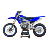
• Make sure that the projection “a” on the con-
necting rod cap faces the same direction as the
“Y” mark “b” on the connecting rod.
• Make sure the “Y” marks “b” on the connecting
rods face towards the left side of the crank-
shaft.
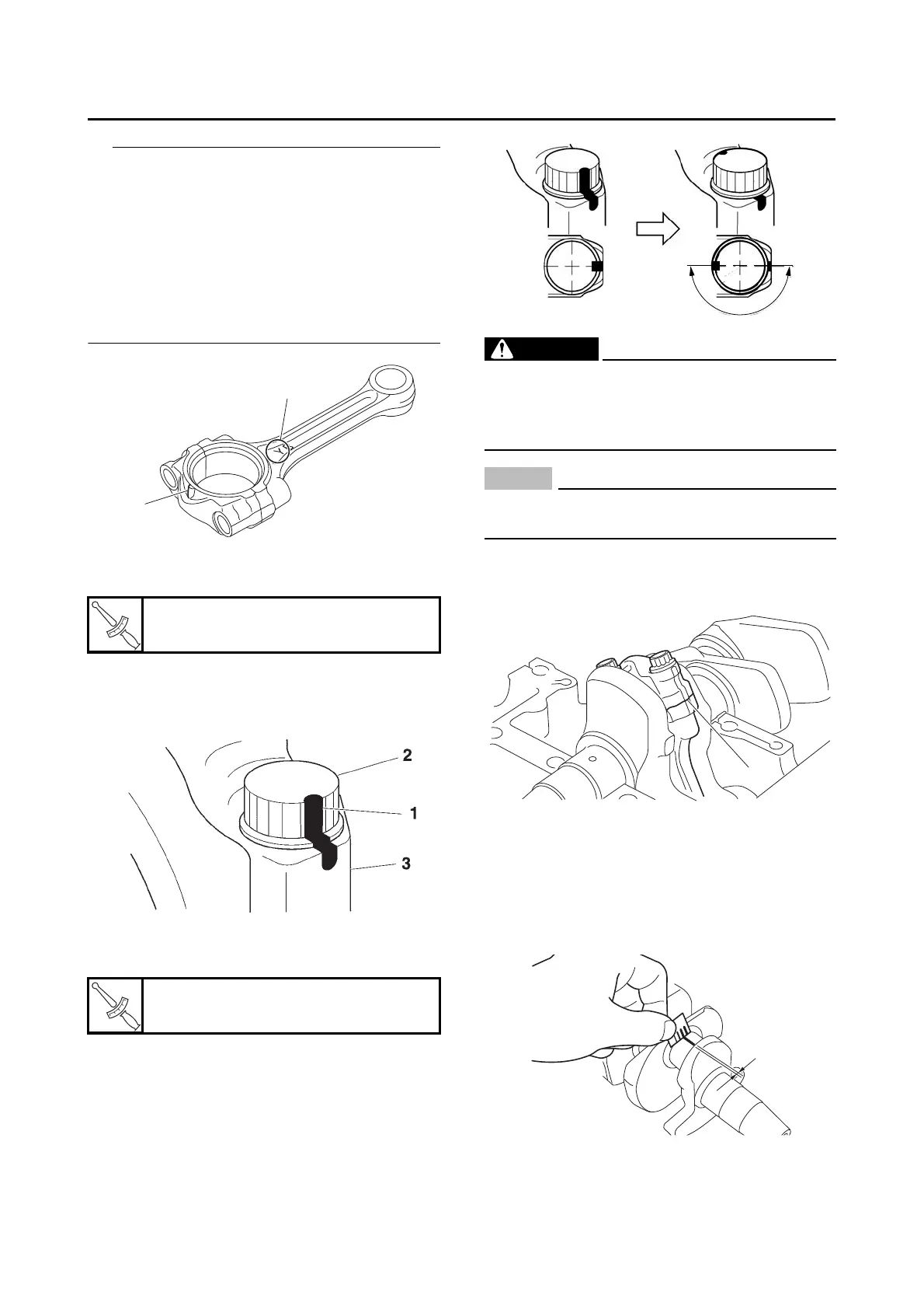
g. Tighten the connecting rod bolts with a
torque wrench.
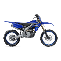
h. Put a mark “1” on the corner of the connect-
ing rod bolt “2” and the connecting rod cap
“3”.
i. Tighten the connecting rod bolts further to
reach the specified angle 180°.
WARNING
EWA16610
If the bolt is tightened more than the speci-
fied angle, do not loosen the bolt and then re-
tighten it. Instead, replace the bolt with a new
one and perform the procedure again.
NOTICE
ECA20890
Do not use a torque wrench to tighten the
bolt to the specified angle.
j. After the installation, check that the section
shown “a” is flush with each other by touch-
ing the surface.
k. Remove the connecting rod and big end
bearings.
l. Measure the compressed Plastigauge®
width “e” on the crankshaft pin. If the crank-
shaft-pin-to-big-end-bearing clearance is
out of specification, select replacement big
end bearings.
2. Select:
• Big end bearing (P
1
–P
3
)
Connecting rod bolt (1st)
20 N·m (2.0 kgf·m, 15 lb·ft)
Connecting rod bolt (final)
Specified angle 180°
 Loading...